2. Installation, Piping, and Wiring
83
TI 11B08A01-01E
n Ethernet (twisted pair) (M) (L)
CAUTION
(M)cable:
Requiredmaximumallowabletemperatureofthecablesdependsonthetemperatureclass
of the instrument and the actual ambient temperature. Use cables with maximum allowable
temperature shown in the table below.
Temperature Class T1, T2 T3 T4
Maximum allowable
temperature of cable
Ambient temp.
Up to 30°C Up to 35°C Up to 40°C 60°C
31 to 36°C 36 to 40°C 41 to 45°C 65°C
37 to 43°C 41 to 45°C 46 to 50°C 70°C
44 to 50°C 46 to 50°C 75°C
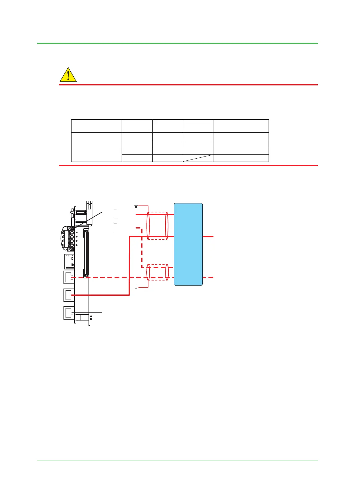
Connect the twisted pair cable of the RJ-45 connector to the CPU card.
The CPU card is labeled “CTRL.CPU”.
1
2
3
4
1
2
3
4
(M)
(M)
+
-
+
-
24V DC
24V DC
(L)
(L)
*1
*2
*2
V +
V -
V +
V -
GC
A
USER
A
GC
B
USER
B
*1
*1
*1
*1
Signal interrupter
K9806AA (rack-mounted type)
K9806AB (desk-top type)
*1: This is not used for FM-Y, CSA-Y.
*2: The ground wire is connected to the earth bar.
Connected to the operation panel
For dual
Figure 2.25 Ethernet (twisted pair cable)
The external I/O cutoff output (power cutoff signal) (L) is also wired.
The shield is grounded at the earth bar shown in Figure 2.24. Remove the cover on the upper
right of the electronics section and perform wiring.
Sep. 07, 2017-00

 Loading...
