2. Installation, Piping, and Wiring
65
TI 11B08A01-01E
(g) Steam pipe
This is necessary for heating the sample with steam.
Connectthepipingbetweenasteamsupplythatcanprovidetherequiredpressure(see
Operation Data) and the analyzer STEAM IN port.
(h) Venting pipes
Theseareusedforbackushventing,foreushventing,detectorventing,etc.Withaventheader,
the piping is provided. Without a vent stack, install piping to the vent stack.
Use large pipes for venting to minimize pressure losses.
Connect venting pipes of 1/4 inch for FID/FPD or 1/8 inch for others to about a 2-inch header.
When ejector suction is used in the sample outlet system, connect the venting pipes to the
downstream of the vent header with a pipe of I.D. 10 mm or more.
CAUTION
Please keep safety in mind because the sample vent is usually open to the atmosphere.
Whenthesampleventisconnectedtothearestack,pleaseconsiderthepressureandtheow
rate of the stack.
(i) Steam drain pipe
This is used to drain the condensate of the steam for heating the sample.
Connect the piping from the steam trap of the analyzer and also from the condensate drain piping
port (CONDENSATE OUT), if provided, to the drain pit on the down-grade.
(j) Pipes for external valves
These are used for piping between the analyzer valve actuating pneumatic outlet and the
external sampling system to actuate the stream valves and atmospheric balance valves provided
in the external sampling system. Connect the piping properly according to the piping diagram.
Use stainless steel of O.D. 6 mm or 1/4 inch.
2.3 Wiring
See “1.1 Wiring and Piping Diagram” for wiring.
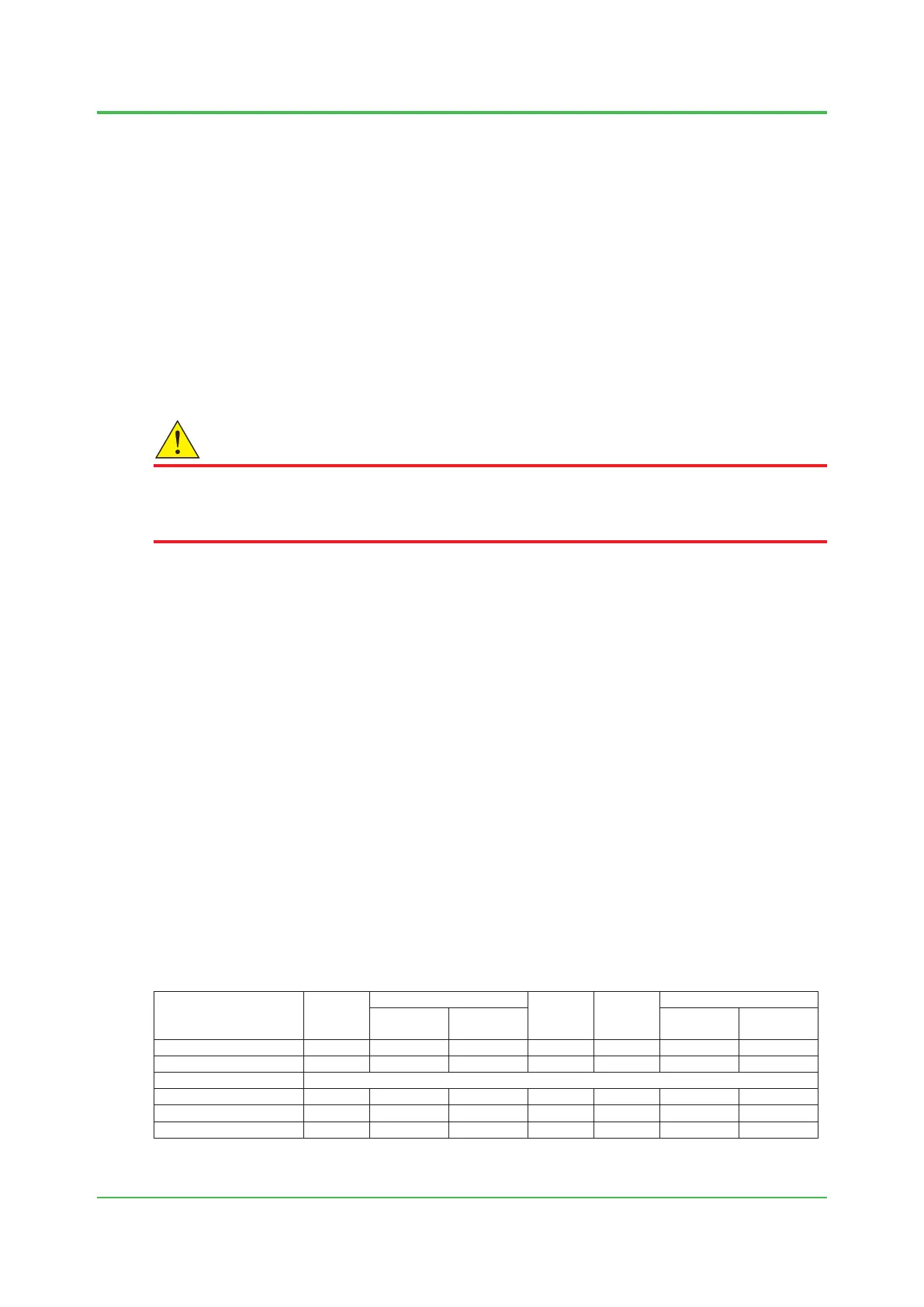
Notethatthespecicationsdeterminesthenumberoftheprotectionsystem,whichresultsin
different wiring.
Table 2.3 Number of protection system
Explosionproof
Specications
Type 1
(100)
Type 2 (120)
Type 3
(222)
Type 4
(230)
Type 5 (110)
100 V
(-A, B, C, D)
200 V
(-E, F, G, H)
100 V
(-A, B, C, D)
200 V
(-E, F, G, H)
TIIS (-T) 1 2 1 2 2 — —
FM-X(-F),CSA-X(-C) 1 2 1 2 2 2 1
FM-Y (-G), CSA-Y (-D) 0
ATEX(-A) 1 2 1 2 2 2 1
IECEx (-E) 1 2 1 2 2 2 1
NEPSI (-P) 1 2 1 2 2 2 1
(): Sufxcodes
Sep. 07, 2017-00

 Loading...
