2. Installation, Piping, and Wiring
61
TI 11B08A01-01E
(5) Condensate drain (CONDENSATE OUT)
(6) Steam (STEAM IN)
(7) Steam drain (STEAM OUT)
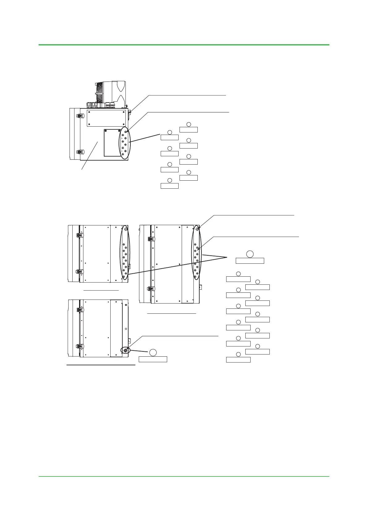
AIR OUT 1
AIR OUT 2
AIR OUT 3
AIR OUT 4
AIR OUT 5
AIR OUT 6
AIR OUT 7
AIR OUT 8
Air outlet for stream swiching valve (A)
6mm or 1/4” tube
Vent for protective gas (instrumental air)
(open to the atmosphere)
Control unit
Figure 2.6 Right side of control unit
SAMPLE 1 OUT
PURGE AIR
SAMPLE 2 IN
SAMPLE 1 IN
SAMPLE 2 OUT
CARRIER 1
CARRIER 2
H
2
MAKE UP
BURNER AIR
ATM 1
ATM 2
PURGE AIR
Protective gas (instrumental air) inlet (B)
Rc1/2 or 1/2NPT
Large isothermal oven
Protective gas (instrumental air) inlet (B)
Rc1/4 or 1/4NPT
Inlet/outlet for sample gas,
carrier gases, etc. (C)(D)(E)(F)(G)(H)
6mm or 1/4” tube
Programmed temperature oven
Isothermal oven
Figure 2.7 Left side of isothermal oven, large isothermal oven, and programmed temperature oven
Sep. 07, 2017-00

 Loading...
