2. Installation, Piping, and Wiring
91
TI 11B08A01-01E
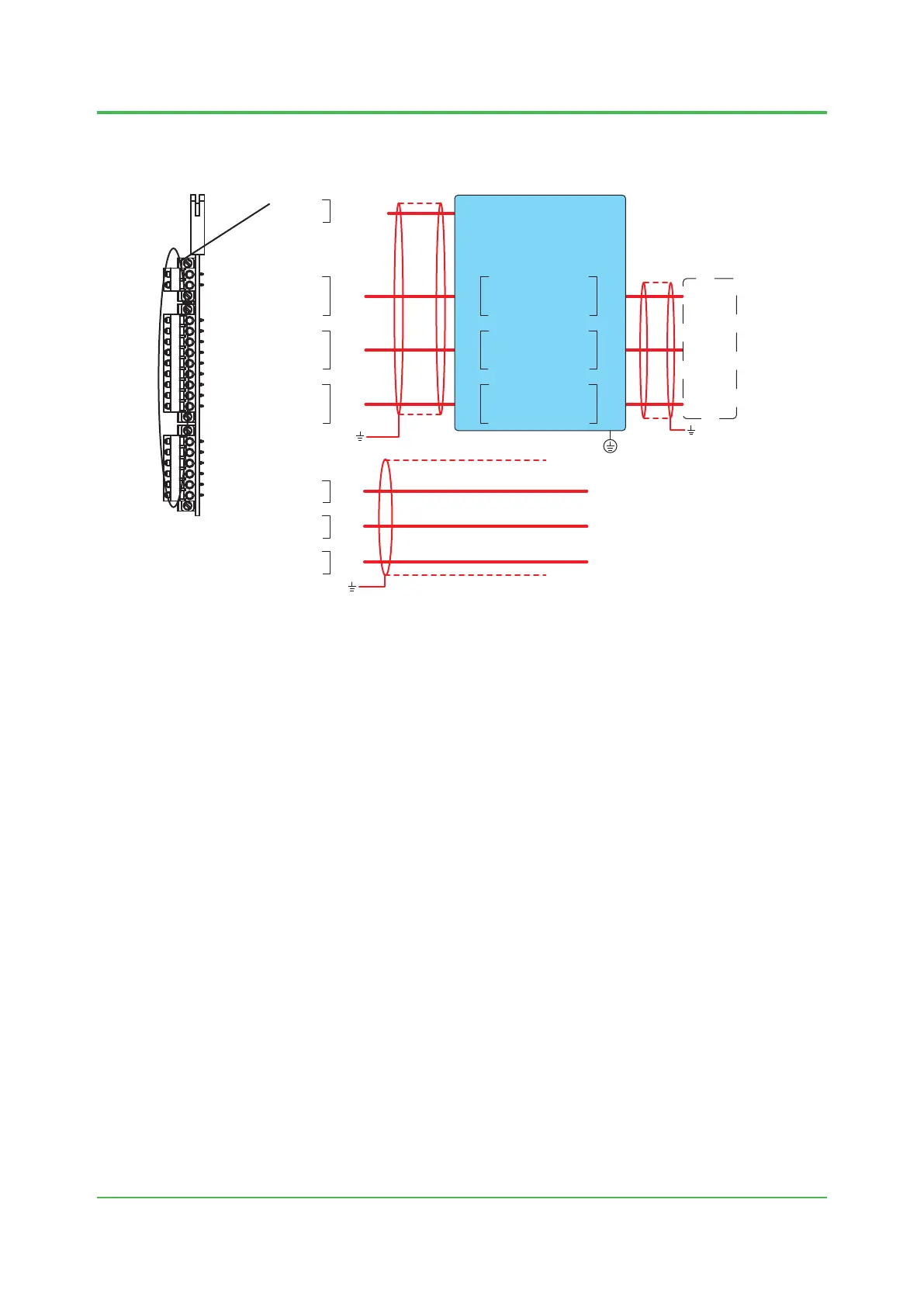
l Contactinput/output(AC)(Code:6)(F)(G)(L)
1
2
11
12
13
14
15
16
17
18
19
21
22
23
24
25
26
1
2
11
12
13
14
15
16
17
18
19
21
22
23
24
25
26
DI1
DI2
DI3
+
-
+
-
+
-
(F)
(F)
(F)
V1 +
V1 -
24V DC
(L)
(G)
(G)
(G)
*1
*1
*1
*2
DO1
DO2
DO3
DO1
DO2
DO3
DO1
DO2
DO3
V +
V -
*3
*2
*4
11 NO
12 COM
13 NO
14 COM
15 NO
16 COM
NO 31
COM 32
NO 33
COM 34
NO 35
COM 36
NO
COM
NO
COM
NO
COM
K9806AN
*1: This is not used for FM-Y, CSA-Y.
*2: The ground wire is connected to the earth bar.
*3: The ground wire is connected to the earth terminal on site.
*4: The protection ground is connected to Class D ground (less than 100 Ω of
grounding resistance), which is nearest to signal interrupter.
Signal interrupter
Figure 2.35 Wiring for a contact input/output card
The contact input/output card is labeled “DIO”.
The external I/O cutoff output (power cutoff signal) (L) is also wired.
The shield is grounded at the earth bar in Figure 2.24. Remove the cover on the upper right of the
electronics section and perform wiring.
Sep. 07, 2017-00

 Loading...
