5-2
IM 04L51B01-01EN
Calibration Procedure
1
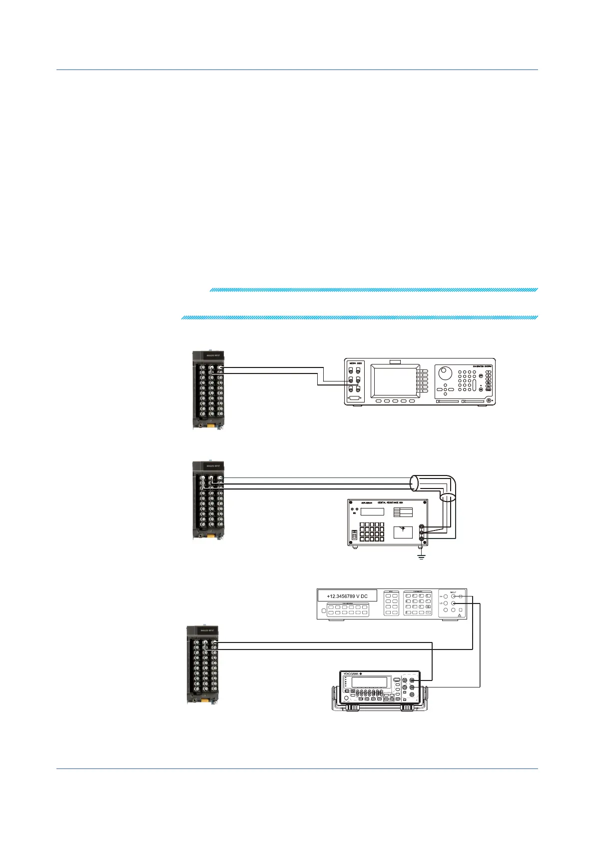
Wire the GX/GP and the calibration instruments as shown in the following figure, and
adequately warm up the instruments (the warm-up time of the GX/GP is at least 30
minutes).
2
Check that the operating environment such as ambient temperature and humidity is
within the standard operating conditions (see “General Specifications”).
3
Apply appropriate input signals corresponding to 0, 50, and 100% of the input range
and calculate the errors from the readings. For current (mA) modules, the error is
determined from the difference between the measured value and the digital multimeter
value. If the error does not fall within the accuracy range of the specifications, servicing
is required. Contact your nearest YOKOGAWA dealer.
You can also perform the A/D calibration and adjust the GX/GP within the accuracy
specifications. Follow the instructions in section 5.1.3, “Performing A/D Calibration and
Adjusting the Input Accuracy.”
Note
For thermocouple inputs, you must measure the temperature of the input terminal and apply a
voltage taking into account the reference junction temperature.
DC Voltage Measurement
CH1
Hi
Lo
DC voltage/current standard
Wiring to the first channel
of the module to calibrate
(Channel ��01)
+
–
Temperature Measurement Using an RTD
b
B
A
CH1
H
L
G
Resistance standard
The resistance of three
lead wires must be equal.
Wiring to the first channel
of the module to calibrate
(Channel ��01)
Current(mA)InputModules
+
-
CH1
+
-
GS200
DC VOLTAGE/CURRENT SOURCE
SAMPLE
ERROR
REPEAT
STORE
REMOTE
ERROR
LOCAL
ESC
POWER
NUM
LOCK
1 2 3 4 5
BS
RANGE
6 7 8 9 0
UTILITY
SETUP
LIMIT
MEASURE
PROGRAM
END
DEL
HOLD
STEP
RUN
PROGRAM
OUTPUT
V
mV
mA
SRQ
ENTER
SENSE OUTPUT
32V
MAX
0.5V
MAX
32V
200mA
MAX
Hi
Lo
42V
10mA
PEAK
G
G TERM 250 V PEAK TO
Digital multimeter
.
5.1 Maintenance
 Loading...