5-4
IM 04L51B01-01EN
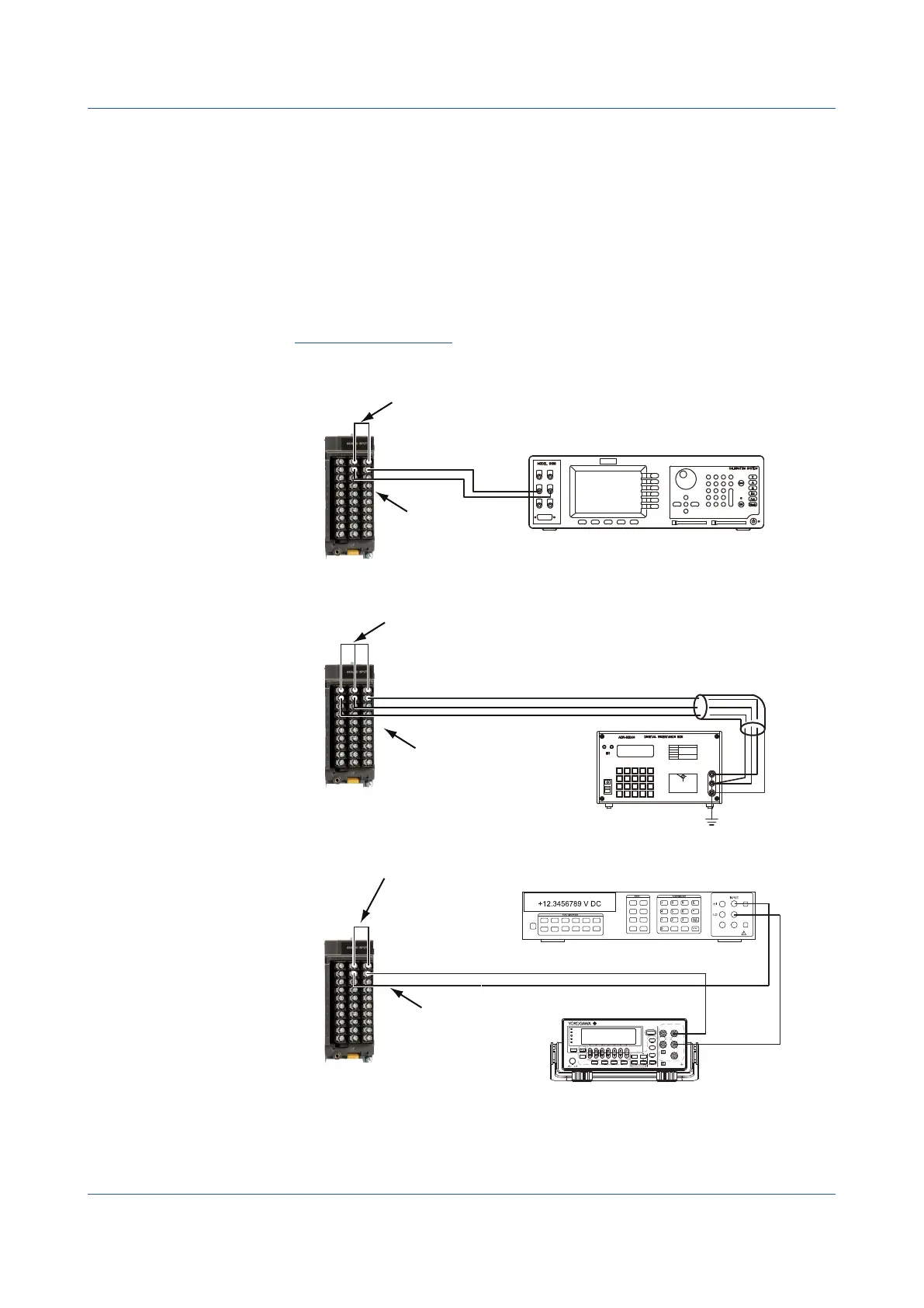
5.1.3 Performing A/D Calibration and Adjusting the Input Accuracy
Preparing the Instruments
1
Wire the GX/GP and the calibration instruments as shown in the following figure, and
adequately warm up the instruments (the warm-up time of the GX/GP is at least 30
minutes).
2
Check that the operating environment such as ambient temperature and humidity is
within the standard operating conditions (see “General Specifications”).
Operation complete
Wiring for DC voltage range
Wiring for RTD range
CH1
CH2
CH1
CH2
+
–
DC voltage/current standard
Hi
Lo
Make the resistance of three lead wires equal.
b
A
Resistance standard
H
L
G
B
A
B
b
Short the input terminal of CH1 (apply 0 V)
Short the input terminal of CH1 (connect 0 Ω)
Input terminal of CH2
Input terminal of CH2
CH1
CH2
Short the input terminal of CH1 (supply 0 A)
Wiring Current (mA) Input Modules
Input terminal of CH2
+
–
GS200
DC VOLTAGE/CURRENT SOURCE
SAMPLE
ERROR
REPEAT
STORE
REMOTE
ERROR
LOCAL
ESC
POWER
NUM
LOCK
1 2 3 4 5
BS
RANGE
6 7 8 9 0
UTILITY
SETUP
LIMIT
MEASURE
PROGRAM
END
DEL
HOLD
STEP
RUN
PROGRAM
OUTPUT
V
mV
mA
SRQ
ENTER
SENSE OUTPUT
32V
MAX
0.5V
MAX
32V
200mA
MAX
Hi
Lo
42V
10mA
PEAK
G
G TERM 250 V PEAK TO
DC current source
Digital multimeter
.
5.1 Maintenance
 Loading...