5-5
IM 04L51B01-01EN
Maintenance and Troubleshooting
5
Performing A/D Calibration and Adjusting the Input Accuracy
For details on switching to the A/D calibration mode when you are using the advanced
security function (/AS option), see section 2.3.1, “Logging In,” in the Advanced Security
Function (/AS) User’s Manual (IM 04L51B01-05EN).
1
Tap the MENU key, Browse tab, Initialize Calibration, and menu A/D calibration.
The A/D calibration call-up screen appears.
2
Tap Execute.
A screen appears for you to conrm the switch to A/D calibration mode.
3
Tap OK.
The GX/GP restarts and enters A/D calibration mode.
4
Select the unit in which the module to calibrate is installed, and tap Next.
The module selection screen appears.
5
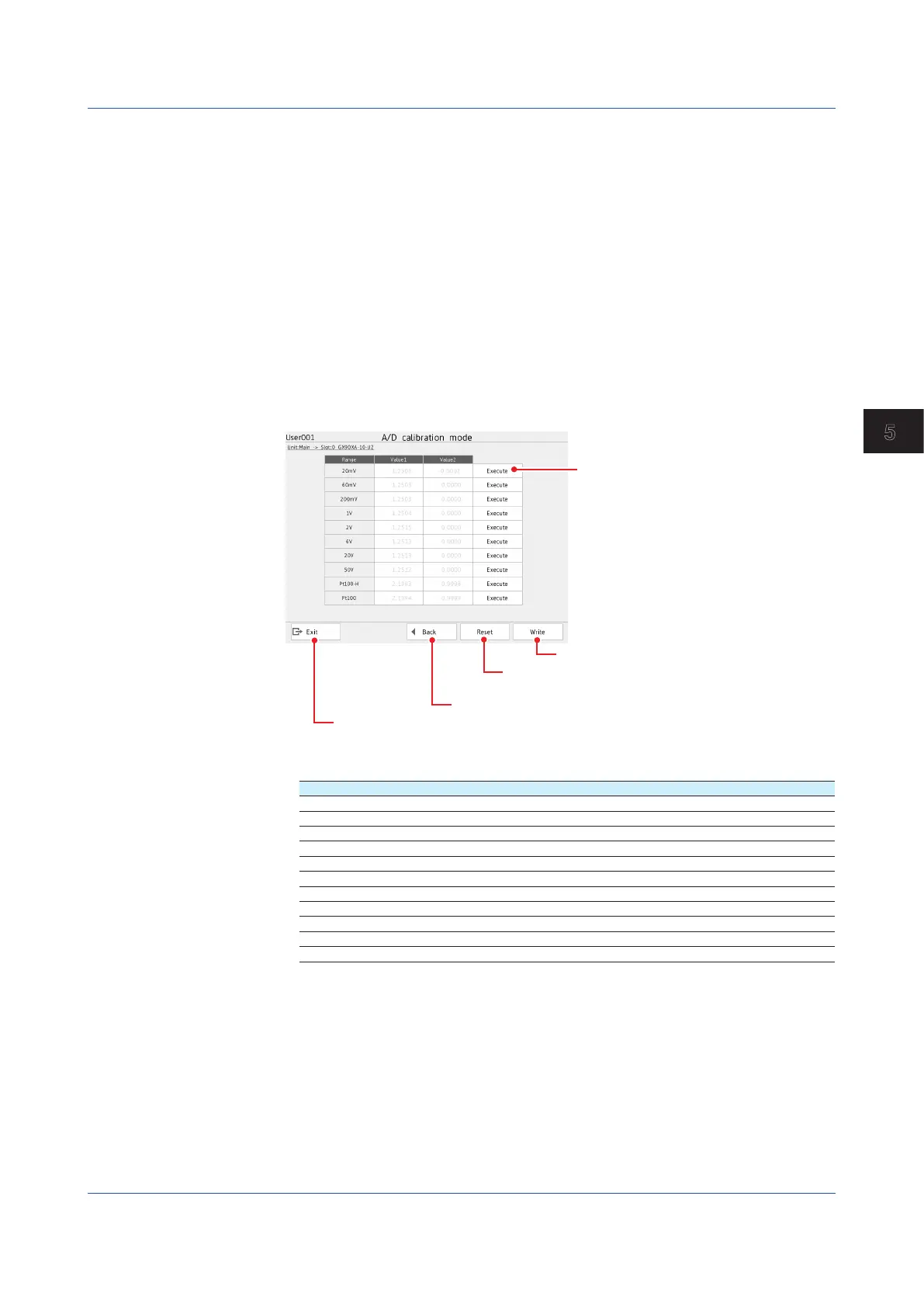
Select the module to calibrate, and tap Next.
Saves calibration values
Returns the calibration values to their
factory defaults
Returns to the module selection screen
Exits from calibration mode
Calibrate the selected range.
6
For each calibration range, apply the reference values indicated in the table below.
Range CH1 CH2
20 mV 0 mV (Short circuit) 20 mV
60 mV 0 mV (Short circuit) 60 mV
200 mV 0 mV (Short circuit) 200 mV
1 V 0 V (Short circuit) 1 V
2 V 0 V (Short circuit) 2 V
6 V 0 V (Short circuit) 6 V
20 V 0 V (Short circuit) 20 V
50 V 0 V (Short circuit) 50 V
Pt100-H
1
0 Ω (Short circuit) 160 Ω
Pt100
1
0 Ω (Short circuit) 400 Ω
20mA
2
0 A (short) 20mA
1 Range calibration of RTDs is not applicable to the electromagnetic relay type (Type suffix code
-T1) or low withstand voltage relay type ((Type suffix code -L1)) analog input module.
2 For only the analog input modules of the current input type (Type suffix code -C1)
7
Tap Execute for the range you want to calibrate.
While calibration is in progress, a message indicating this appears. When the calibration is com-
plete, the message “Execution is complete” and the calibration value appear.
8
Repeat step 5 for every range.
5.1 Maintenance
 Loading...