JOHNSON CONTROLS
23
SECTION 2 - START-UP AND OPERATION
FORM 102.20-OM2
ISSUE DATE: 6/01/2015
2
FAN
TYPE
FAN
CLASS
FAN SIZE k n
FAN
TYPE
FAN
CLASS
FAN SIZE k n
MPQS 1 330 5968.62 N/A MPQN 2 330 5968.62 N/A
MPQS 2 330 5968.62 N/A MPQN 3 330 5968.62 N/A
MPQS 3 330 5968.62 N/A MPQN 1 365 7290.21 N/A
MPQS 1 365 7290.21 N/A MPQN 2 365 7290.21 N/A
MPQS 2 365 7290.21 N/A MPQN 3 365 7290.21 N/A
MPQS 3 365 7290.21 N/A MPQN 1 402 8869.55 N/A
MPQS 1 402 8869.55 N/A MPQN 2 402 8869.55 N/A
MPQS 2 402 8869.55 N/A MPQN 3 402 8869.55 N/A
MPQS 3 402 8869.55 N/A MPQN 1 445 10827.92 N/A
MPQS 1 445 10827.92 N/A MPQN 2 445 10827.92 N/A
MPQS 2 445 10827.92 N/A MPQN 3 445 10827.92 N/A
MPQS 3 445 10827.92 N/A MPQN 1 490 13135.01 N/A
MPQS 1 490 13135.01 N/A MPQN 2 490 13135.01 N/A
MPQS 2 490 13135.01 N/A MPQN 3 490 13135.01 N/A
MPQS 3 490 13135.01 N/A SF 2 165 1361.00 N/A
SF 2 105 592.00 N/A SF 2 182 1673.00 N/A
SF 2 122 842.00 N/A SF 2 200 1942.00 N/A
SF 2 135 963.00 N/A SF 2 222 2454.00 N/A
SF 2 150 1147.00 N/A SF 2 245 3010.00 N/A
TABLE 2 - AIR MEASURING DEVICE CONNECTIONS (CONT'D)
Air Measuring at the Fan Inlets
• COMETER is a probe attached to the fan bearing
support on Comefri Forward Curve fans from size
7 x 7 up to 18 x 18. The probe is located on the
outboard side of the housed fan assembly. The
probe is piped to the negative (-) port of a factory
mounted transducer on the fan wall. The positive
(+) port is left open to the fan section. Wiring
is not provided to the transducer unless factory
packaged controls were selected.
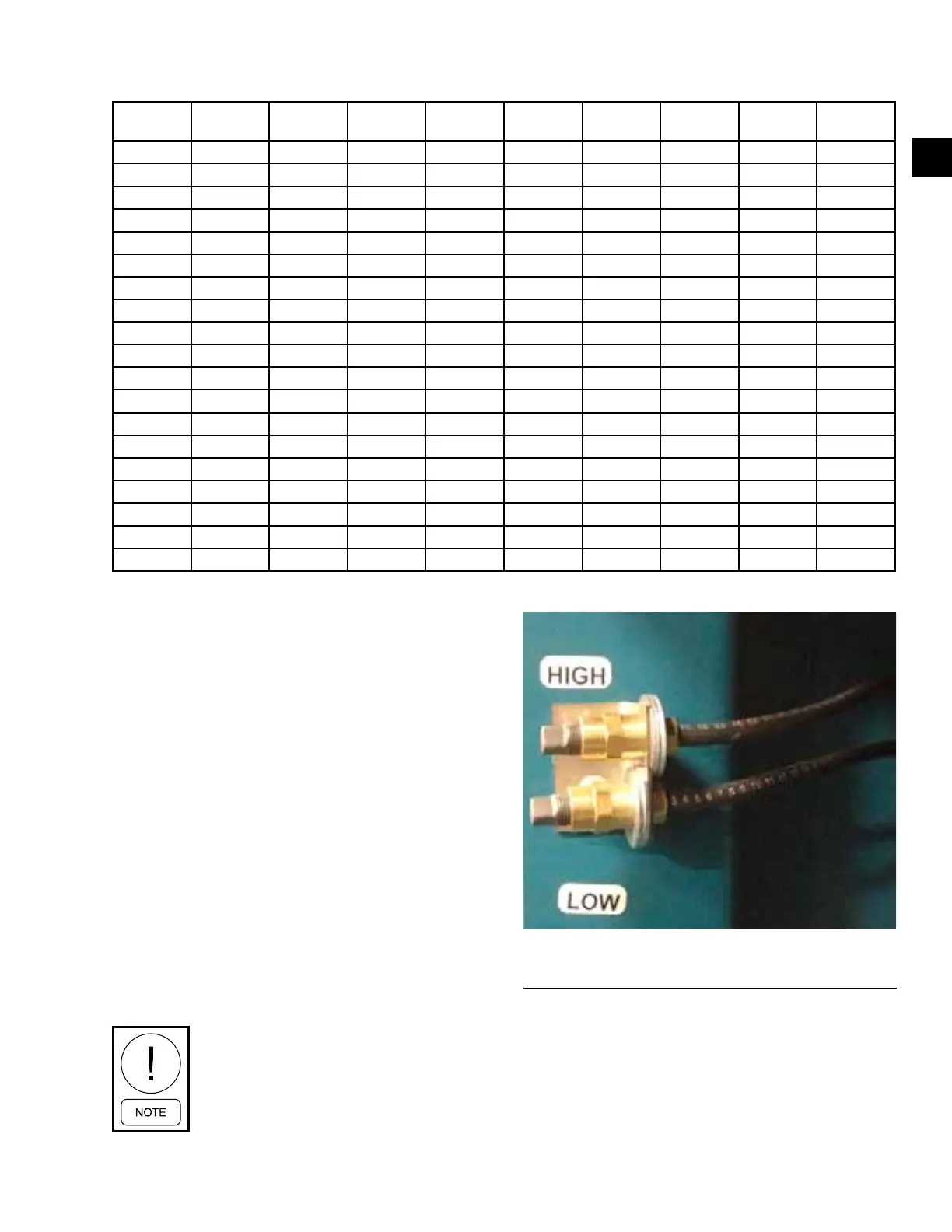
• PIEZORING (PIEZOMETER) is atting or se-
riesofttingsintheinletcone(s)ofhousedfans
larger than 18 x 18 and all sizes of Plenum fans
that are combined into a single connection piped
to the negative (-) port of a factory mounted trans-
ducer on the fan wall. The positive (+) port is left
open to the fan section. Wiring is not provided
to the transducer unless factory packaged controls
were selected.
The fan manufacturer does not recom-
mend placement of the ow measuring
probes inside the fan inlet cone in the
path of airflow. These devices create
disturbances and unpredictable perfor-
mance losses.
FIGURE 11 - HIGH AND LOW CONNECTIONS FOR
AN IN FAN AIR MONITORING SYSTEM
LD17231