JOHNSON CONTROLS
28
FORM 102.20-OM2
ISSUE DATE: 6/01/2015
SECTION 2 - START-UP AND OPERATION
Airow Monitoring Station with Louvers/
Hoods (Outdoor AHU)
Use the following equation to determine the correct
jumper setting for your application:
CFM=(FREE AREA*Ka)*Pams (1/m), where Ka = 3833
Pams = Range of transmitter, and (l/m) = 0.52.
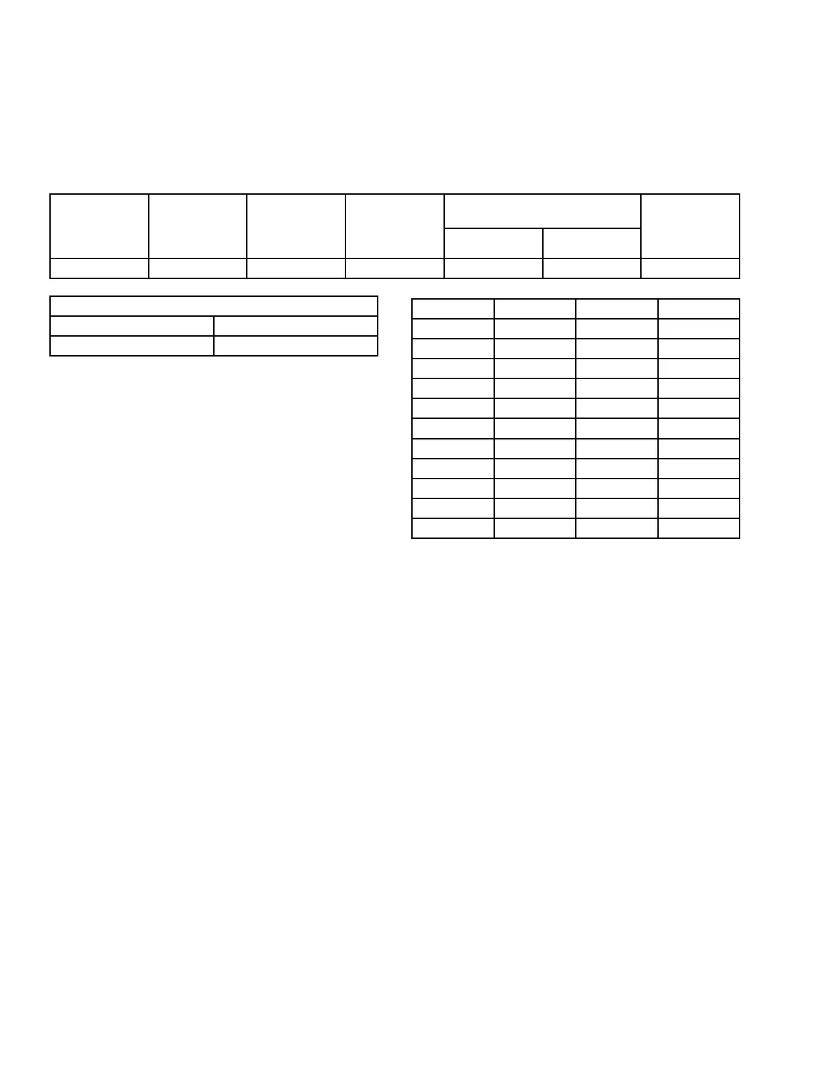
TABLE 4 - OUTDOOR UNIT EXAMPLE
UNIT NAME
FAN DESIGN
FLOW (CFM)
AMS
SENSING (%)
AMS O.A.
SETPOINT
(CFM)
AMS-60 SENSING DAMPER
DIMENSIONS 100% SENSING
AMS
SENSING
AREA
(SQ. FT.)
"A" DIM. (IN.) "B" DIM. (IN.)
AHU-01 21370 25 7000 22.5 32.75 5.1
RANGE: 0.0 TO +0.25
MIN MAX
0 0.25
Recommended operating range is 300-2,000 FPM. Op-
eration outside these parameters is not recommended.
VOLTS PAMS CFM FPM
0 0.00 0.0 0.00
1 0.03 2880.7 564.84
2 0.05 4130.8 809.96
3 0.08 5100.4 1000.07
4 0.10 5923.4 1161.45
5 0.13 6652.2 1304.35
6 0.15 7313.7 1434.06
7 0.18 7924.1 1553.75
8 0.20 8493.9 1665.47
9 0.23 9030.4 1770.66
10 0.25 9538.9 1870.38
Locating and Installing Actuators
Johnson Controls standard actuators are direct coupled
on the damper jackshaft. Refer to the instructions in
the Solution XT Air Handling Units - Installation and
Assembly Manual (Form 102.20-N1) and York Custom
Air Handling Units - Installation and Assembly Man-
ual (Form 102.20-N3) to install the Johnson Controls
actuators.
Damper Blade Orientation
Use the following instructions to orient the damper
blades.
Return Air and Mixing Dampers
1. Position the blades so that they will be open after
the actuator is installed, which will be the damp-
ers spring return position.
2. Note whether the damper shaft is rotated clock-
wise or counterclockwise.
Outside Air and Exhaust Air Dampers
1. Position the damper blades so that they will be
closed with the power off, which will be the damp-
ers spring return position. Note if the damper shaft
is rotated clockwise or counterclockwise.
2. With the actuator shaft clamp tightened to the
damper jackshaft, and the damper shaft complete-
ly rotated to its proper position, manually operate
the actuator to its fully actuated position, using the
crank arm provided with the actuator.
3. Release the spring to allow the damper to go back
to its original position, which will verify the ac-
tuators spring rotation and stroke.
4. Set the damper actuators rotation selector switch
to the proper rotation required to actuate the
damper. e damper actuator will always be op-
posite the spring return rotation.
Energize Fan Motors
Use the following instructions to energize the fan mo-
tors:
1. Observe the fan(s) for smooth operation.
2. Check the motor nameplate for the full load amp
(FLA) rating.
3. Check the current draw of each leg of each motor.
 Loading...


