JOHNSON CONTROLS
58
FORM 102.20-OM2
ISSUE DATE: 6/01/2015
SECTION 3 - MAINTENANCE
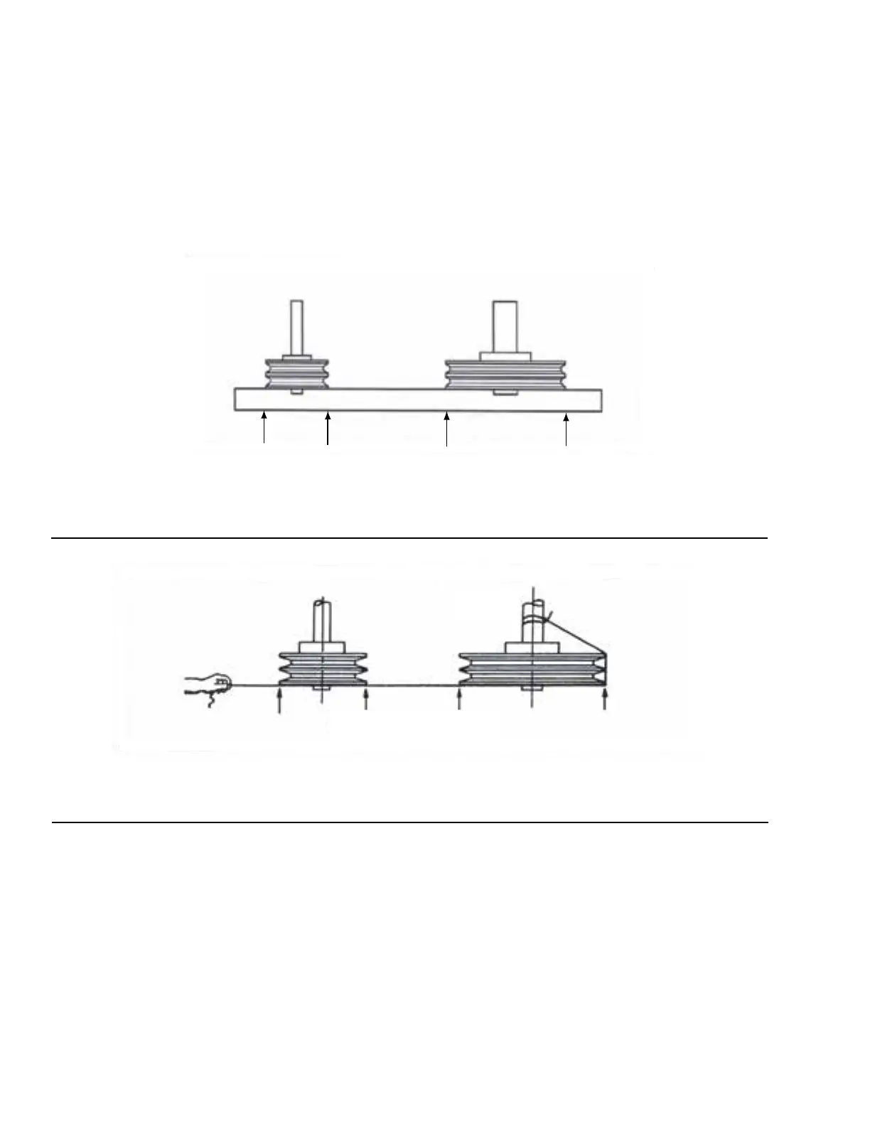
Using a Straightedge
Place a straightedge against the outer edge of the
sheaves. Figure 48 on page 58 shows the four points
where the straight edge should touch the sheaves. The
straight edge should cross the sheaves at the widest
possible part of the sheave.
Using a String
Tie a string around either shaft and pull it around and
across the outer edge of both sheaves as shown in Fig-
ure 49 on page 58 shows how the string should touch
four points when the drive is properly aligned.
If alignment is different than described, refer to Belt
Replacement Tensioning and Sheave Alignment for Top
Mount on page 58 later in this section.
FIGURE 48 - ALIGNMENT USING STRAIGHT EDGE
LD09646
Straight Edge Touching Sheaves At Points Indicated By Arrows
ALIGNMENT USING STRAIGHT EDGE
FIGURE 49 - ALIGNMENT USING STRING
LD09646a
Cord Touching Sheaves At Points Indicated By Arrows
ALIGNMENT USING STRING
Cord Tied To Shaft
BELT REPLACEMENT TENSIONING AND
SHEAVE ALIGNMENT FOR TOP MOUNT
Use the following instructions to align the sheaves on
the motor base:
1. To remove the old belt, loosen the mounting hard-
ware on the drive side of the motor base. The drive
side has two adjusting screws. Do not increase the
left side more than 1/2 in before increasing the
right side.
2. Remove the tension from the belt on the lower
drive side, using the adjustment screws as shown
in Figure 50 on page 59.
3. After the tension is removed from the belt, loosen
the mounting hardware on the opposite drive side
of the base.
4. Continue to lower both ends of the base until the
belts can be removed as shown in Figure 51 on
page 59.