JOHNSON CONTROLS
26
FORM 102.20-OM2
ISSUE DATE: 6/01/2015
SECTION 2 - START-UP AND OPERATION
The 25/75% Sensing option arrangement is similar to
the 25% Sensing (Min./Max.) option, but allows you
to measure airflow throughout the economizer cycle
also. In this arrangement, the 25% damper would be
for monitoring nominal airflow through the first 25%
down to 3.75% and the 75% damper would be for mon-
itoring the remaining 75%.
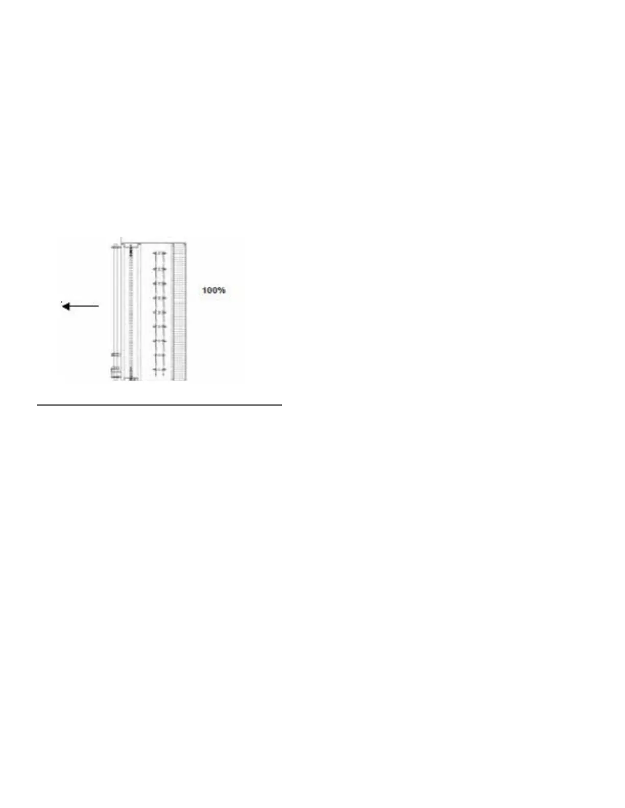
• 100% Sensing Option
The 100% sensing arrangement is a single damper de-
sign used to measure airflow throughout the full range
of the outside air damper down to 15% of nominal air-
flow.
FIGURE 18 - 25%/75% SENSING OPTION
LD17246
The 100% sensing option is the lowest cost option, but
should not be utilized when minimum airflow to be
sensed falls below 15% nominal flow. The 25% Sens-
ing (Min./Max.) and 100% Sensing option arrange-
ments will be the most prevalent.
The 100% Sensing arrangement with the outside and
return air dampers tied to a common actuator, will
usually be the most common configuration and cost-
effective solution. However, areas in which economiz-
er cycles are not often seen and operate primarily in
minimum outside air position, the 25% Sensing option
should be the preferred option for lowest airflow moni-
toring and a cost-effective solution.
In each of the available configurations, the minimum
airflow across the sensing portion of the airflow moni-
toring station is 300 FPM for the indoor AHU and 345
FPM for the outdoor AHU.
Factory Mounted Control Option
The AMS-60 airflow monitoring station may be or-
dered with or without Factory-mounted End Devices.
The Optional End Devices must be selected through
the YorkWorks program and consist of the following:
• Modulating, Spring Return Actuator(s)
• Low Pressure Transducer(s)
YorkWorks will provide all wiring schematics.
Jumper Selections
When selected, the AMS-60 factory provided trans-
ducers technically provides six (6) jumper selections
which allow you to select the appropriate range for
your application. However, only three (3) are appli-
cable to the AMS-60 function. The jumper selections
are as follows: 0-1", 0-.5", and 0-.25". These are field
adjustable. To determine the correct jumper setting for
your application, refer to the equation and examples on
Table 3 on page 27 for indoor AHUs and Table 4 on
page 28 for outdoor AHUs.
Input Power
A 24VAC power supply can be wired into the supply
voltage terminals on the Factory-mounted Actuator
and Transducer.
CFM Input Signal to Damper Actuator
2-10VDC (BELIMO)
0-10 VDC (JOHNSON CONTOLS)
CFM Output Signal from Transducer
0-10VDC
Sequence Of Operation
A 0-10 VDC or 2-10VDC control signal is sent to the
AMS 60 damper actuator from the Building Automa-
tion System (BAS). The BAS maintains the required
cfm by modulating the actuator on the control damper.
The BAS receives a 0-10 VDC signal back from the
transducer, confirming the cfm supplied. Upon loss of
power, the AMS-60 actuator returns to a closed posi-
tion.