JOHNSON CONTROLS
84
FORM 102.20-OM2
ISSUE DATE: 6/01/2015
SECTION 4 - SERVICE AND REPAIR
Adjusting Sheave
1. Before belts are installed, check alignment as
described in Belt Replacement Tensioning and
Sheave Alignment for Top Mount on page 58.
2. If adjustment is required, measure the space be-
tween the straight edge and the sheave.
3. Follow steps 2–5 under Removing Sheave on
page 82 in this section. Move the bushing in
the proper direction the distance measured.
4. Proceed with the instructions in Installing Sheave
on page 82 in this section.
Adjustable Pitch Sheaves (T.B. Woods -
Model JVS)
Tools and Material Required
• Standard mechanic’s hand tools
• Mediumatle
• Torque wrenches (0-250 in-lb)
• Hex (Allen) socket set for torque wrench
• Square and straight edge
• Fine Emery cloth
Removing Sheave
1. Remove the belts.
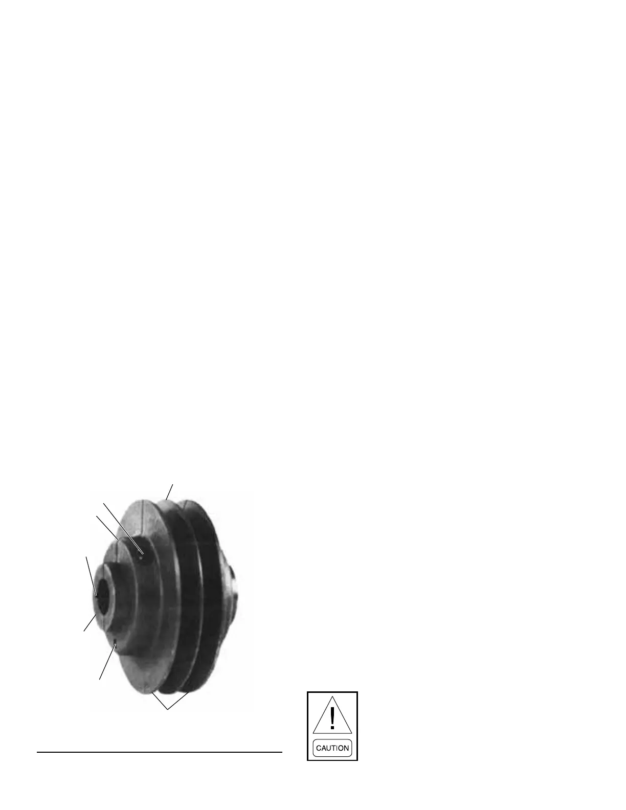
2. Loosen both clamp screws with an Allen wrench
as shown in Figure 91 on page 84.
CLAMP SCREW
SLIP
CENTRAL
SLEEVE
ADJUSTABLE FLANGES
ADJUSTING SCREW
KEYWAY
LD09665a
FIGURE 91 - ADJUSTABLE PITCH SHEAVE (JVS)
3. Clean and remove any burrs from the shaft from
the sheave to the end.
4. Slide sheave off shaft. If tight, insert screwdriver
into slit in central sleeve.
Installing Sheave
1. Loosen the clamp screws on the new sheave.
2. Slide the JVS sheave onto the shaft. Place the fan
and motor sheaves on their respective shafts far
enough to have the shaft exposed past its chamfer,
which will facilitate proper alignment later in the
process.
3. The central sleeve of this sheave is split at one end
only. Install thisend rst as the splitallows the
sheave assembly to be secured to the shaft.
4. Adjust the sheave to the approximate pitch diam-
eter desired. One turn of the adjusting screw will
vary the pitch diameter 0.2 in. Seven turns are re-
quired to adjust the sheave from the minimum to
the maximum pitch diameter.
5. Putslightngerpressureonthefaceoftheadjust-
ableangesnearthesplit(180°fromtheadjust-
ing screw) to permit free and equal movement of
theanges duringpitch adjustments.Otherwise,
tipping and binding may occur.
6. Align the sheave with the companion sheave.
7. If there is a difference of more than 1/8 in. be-
tween the width of the companion sheave and any
adjustable pitch sheave, align them, using Steps
5-6.
8. Alignment procedure for adjustable sheaves:
9. Use a square and straight edge to align the center
orstationaryangeoftheadjustablesheavewith
thecenterangeofthecompanionsheave.
10. Insure the shaft of the motor is parallel to the shaft
of the fan.
11. Tighten the two clamp screws to the following
torque values:
• JVS Model: 130- 160 in-lb. or 13 ft-lb
• All other JVS Models: 325 in-lb or 27 ft-lb
Be careful not to grasp anges in such a
manner as to cock them while tightening
the clamp screws.