JOHNSON CONTROLS
47
SECTION 2 - START-UP AND OPERATION
FORM 102.20-OM2
ISSUE DATE: 6/01/2015
2
age or nuisance thermal cutout tripping.
2. A visual inspection of the heater elements should
be made prior to use of the heater. If physical dam-
age is evident, a Megohm test should be used to
validate the heater elements are safe for use. If a
minimum value of 10 megohms is not achieved
then any damaged elements or ceramic insulators
must be replaced prior to operation.
Electrical Installation
1. Follow the wiring diagram on the inside of the ter-
minal box.
2. Supply connections must be made with copper
wiring rated for 75°C minimum.
3. If supply connections are for 250 volts or greater,
all wiring must be insulated for 600 volts.
4. When making line connections to heater element
terminals FOR FINNED TUBULAR HEATERS
ONLY,applya1/4"wrenchtoatsectionoftermi-
nal immediately below threads. Otherwise damage
to terminal may result.
5. Supply conductors for heaters rated less than 50
KW, must be sized at 125% of rated load. On heat-
ers rated 50 KW and more, the supply conductors
may be sized at 100% of rated load, if indicated on
the wiring diagram. The line current for either a
single or three phase load is calculated as follows:
Single Phase Line Current = KW x 1000
Voltage
Three Phase Line Current = KW x 1000
Voltage x 1.73
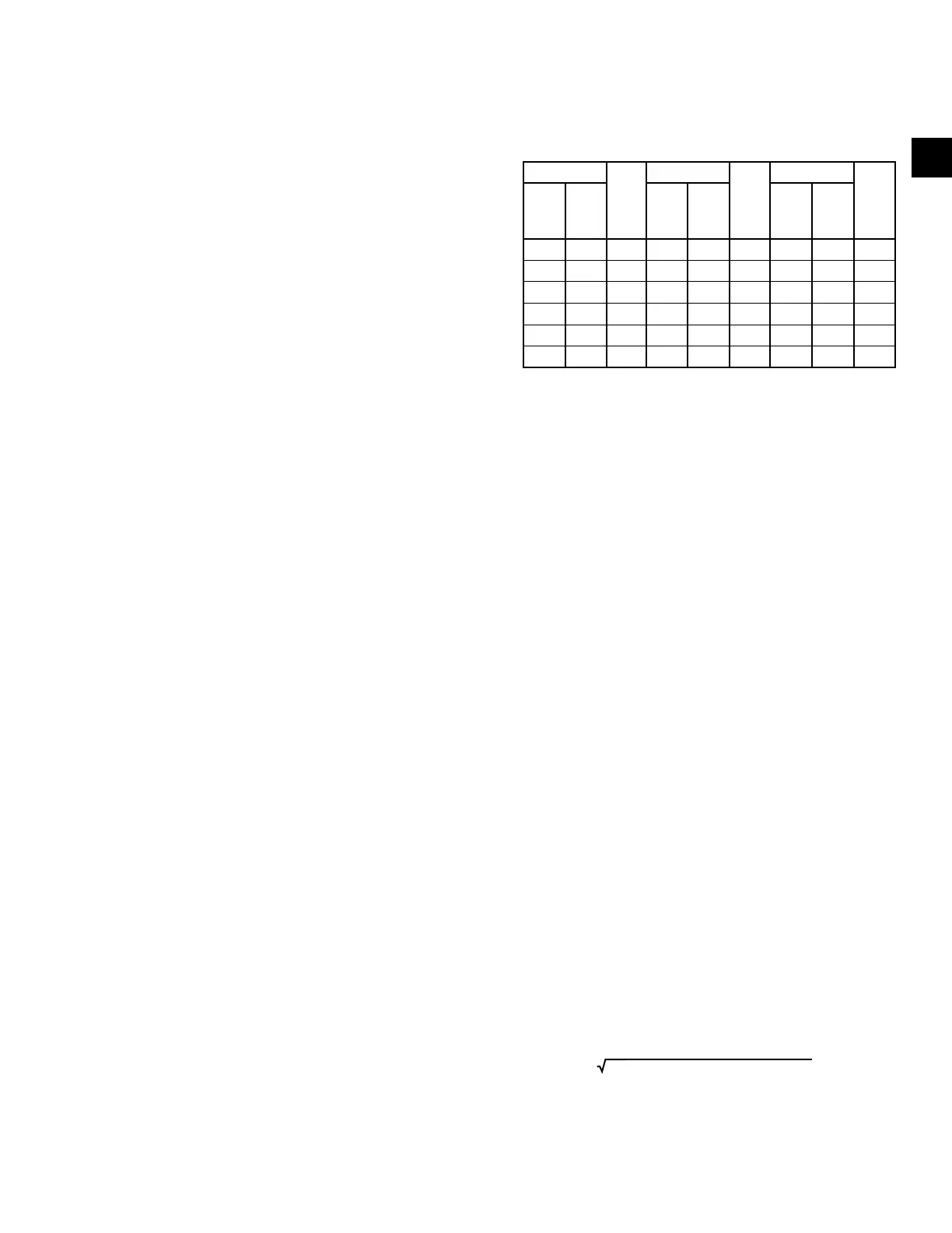
6. The following table shows the maximum current
for 75°C copper wire with not more than three
conductors in a raceway. It is based on the NEC
Table 310-16. The amperages shown are for 125%
and 100% wire sizing. If there are more than three
conductors in a raceway, derate these amperages
per NEC Table 310-15(b)(2)(a).
TABLE 10 - MAXIMUM CURRENT FOR 75°C COP-
PER WIRE
AMPS Wire
Size
Awg/
MCM
AMPS Wire
Size
Awg/
MCM
AMPS Wire
Size
Awg/
MCM
125% 100% 125% 100% 125% 100%
12 14 80 100 3 184 203 4/0
16 12 92 115 2 204 255 250
24 10 104 130 1 228 285 300
40 8 120 150 0 248 310 350
52 65 6 140 175 2/0 268 335 400
68 85 4 160 200 3/0 304 380 500
7. When connecting heaters with more than one
stage,wirestageNo.1sothatitistherststage
on and the last stage off.
8. The heater must be wired so that it cannot oper-
ateunlessair isowingoverit.Thiscan be ac-
complishedbyusingabuilt-inairowswitchand
a remote interlock. See the accompanying wiring
diagram for the method used with this heater and
provide appropriate interlock wiring as illustrated.
This diagram will be located inside of the electric
heater control panel.
9. If not supplied as part of this heater, install a line
disconnect switch or main circuit breaker in ac-
cordance with the NEC. Depending upon the
heater’s location and accessibility, a built-in dis-
connect switch may meet this requirement.
10. All electrical connections in the heater, including
botheld andfactory madeconnections, should
be checked for tightness before operating the
heater. In addition, after a short period of opera-
tion, all connections should again be checked for
tightness.
11. If heater is wired to a heating / cooling thermostat,
use a thermostat with isolating circuits to prevent
possible interconnection of Class 2 outputs.
12. If the heating elements are divided into several
sections with resistance wire between two or more
sections, maximum KW per sq. ft. should be cal-
culated as follows:
Heater nameplate KW
Number of heated sections x
area of one heated section