JOHNSON CONTROLS
85
SECTION 4 - SERVICE AND REPAIR
FORM 102.20-OM2
ISSUE DATE: 6/01/2015
4
12. Install the belts and tighten properly.
13. Recheck the alignment and speed.
Adjusting Sheave
1. To adjust the pitch diameter, loosen both clamp
screws.
2. Remove the belts.
3. Follow Steps 3–8 in Installing Sheave on page
82 in this section.
Adjustable Pitch Sheaves (T.B. Woods -
Model FHP)
Tools and Material Required
• Standard mechanic’s hand tools
• Mediumatle
• Torque wrench (0-250 in-lb)
• Hex (Allen) socket set for torque wrench
• Square and straight edge
• Fine Emery cloth
Removing Sheave
4. Remove the belts.
5. Loosenthesetscrewsontheadjustableange(s)
of the sheave (Allen wrench) as shown in Figure
92 on page 85.
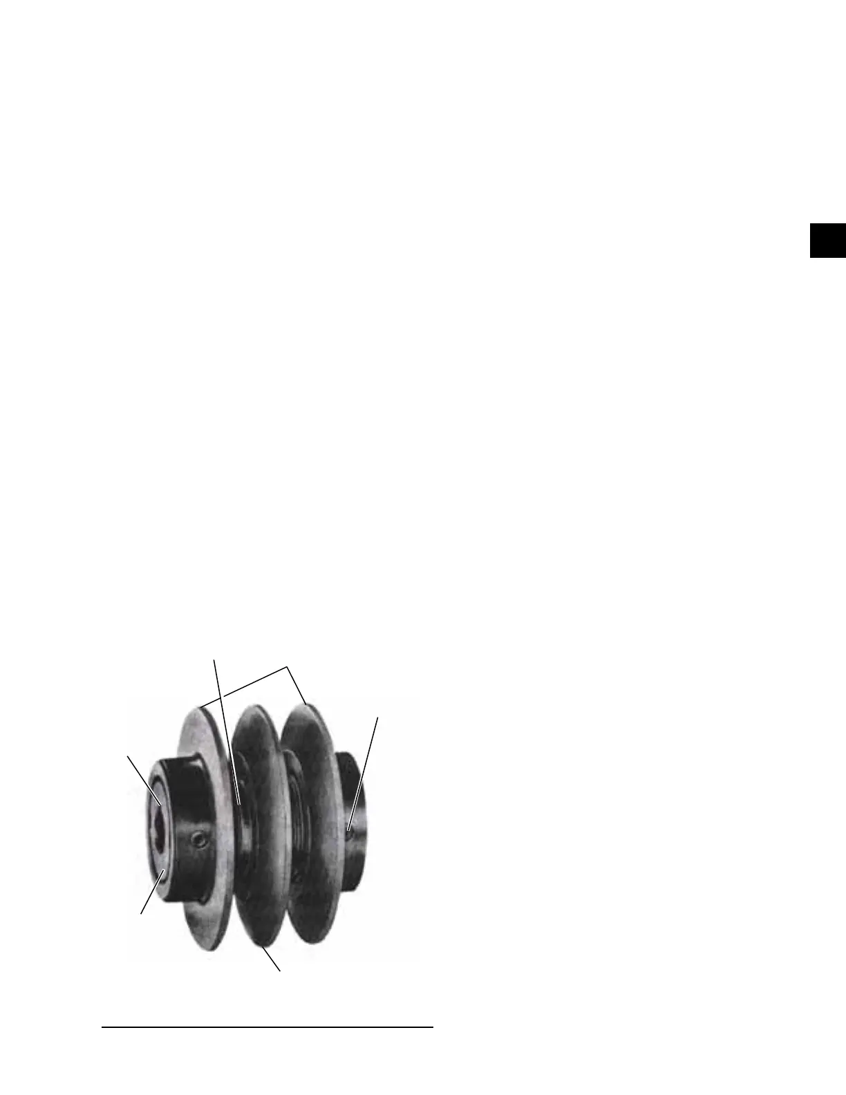
STATIONARY FLANGE
CENTRAL
SLEEVE
ADJUSTABLE FLANGES
KEYWAY
MOUNTING SET SCREW
SETSCREW
LD09666
FIGURE 92 - ADJUSTABLE PITCH SHEAVE (FHP)
6. Screwtheadjustableange(s)opentoexposeand
loosen the mounting setscrew in the central sleeve
over the key.
7. Clean and remove any burrs from the shaft from
the sheave to end.
8. Slide the sheave off of the shaft.
Installing Sheave
1. Loosensetscrewsonadjustableange(s)ofnew
sheave (Allen wrench).
2. Screwtheadjustableange(s)opentoexposeand
loosen the mounting setscrew in the central sleeve
over the keyway.
3. Inspect the shaft and key for any nicks and burrs.
Remove same and clean shaft.
4. Insert the key into the keyway.
5. Slide the new sheave onto the shaft with the
mounting setscrew over the key and toward the
motor.
6. The fan and motor sheaves should be placed on
their respective shafts far enough to have the shaft
exposed past its chamfer, if possible, which will
facilitate ease of alignment later in this process.
7. Align the adjustable sheave’s stationary ange
with the respective ange of the companion
sheave. On adjustable sheaves of two or more
grooves, if there is a difference of more than 1/8"
between the width of the companion sheave and
any adjustable pitch sheave, align using Steps
7–10.
8. Alignment procedure for multiple groove adjust-
able sheaves:
9. Use a square and straight edge to align the center
orstationaryangeoftheadjustablesheavewith
thecenterangeofthecompanionsheave.
10. Insure the shaft of the motor is parallel to the shaft
of the fan.
11. Secure the adjustable sheave to the shaft by tight-
ening the setscrew over the key to the proper
torque value.
12. Adjust the sheave ange(s) to the desired pitch
diameter. Each turn of the ange changes the
pitch diameter approximately 0.2 in. Six turns are
required to adjust the sheave from minimum to
maximum for A or B belts, and seven turns for
5V belts.
 Loading...


