JOHNSON CONTROLS
59
SECTION 3 - MAINTENANCE
FORM 102.20-OM2
ISSUE DATE: 6/01/2015
3
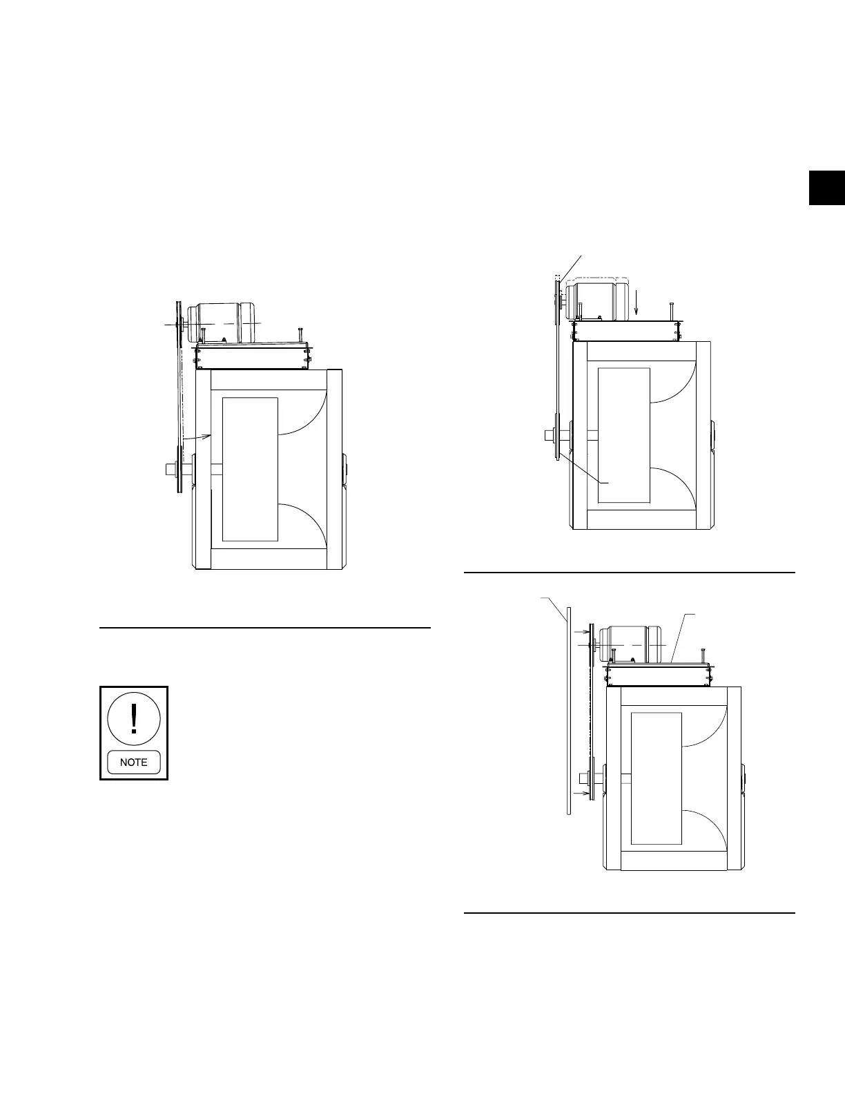
5. After the sheaves are checked for parallel align-
ment as shown in Sheet 1, place the belts on the
sheaves.
6. To take the slack out of the belt(s), start raising the
base in 1/2 in. increments, using the adjustment
screws on both ends.
7. As the belts start to tighten, check for parallel mis-
alignment by placing a straight edge across the
outer face of the sheaves as shown in Figure 52
on page 59. The straight edge should be long
enough to extend past both sheaves.
FIGURE 50 - SHEAVE ANGULAR MISALIGNMENT
LD165676
8. If the sheaves are misaligned as shown in Figure
50 on page 59, raise the opposite drive side.
As the belt tension increases, the opposite
drive side of the belt will rise. Make sure
the mounting hardware on the opposite
drive side is secure.
9. Continue to tighten the belt(s), using the drive
side the adjusting screws.
10. If the sheaves are still misaligned as shown in Fig-
ure 51 on page 59, make sure the belt tension
is correct, then secure the mounting hardware on
the drive side.
11. If the sheaves are still misaligned as shown in Fig-
ure 51 on page 59, make sure the belt tension
is correct, then lower the drive side of the base to
remove to remove the belt tension.
12. Loosen the mounting hardware on the opposite
drive side, and raise or lower the base according-
ly, and repeat Steps 6–10.
13. Mark the position of the base's opposite drive
side mounting hardware before lowering the base,
which may help determine where to secure the
hardware the next time the belt is replaced.
14. Reinstall the belt.
SHEAVE
BELT
FAN
SHEAVE
MOTOR
PLENUM
FAN
FIGURE 51 - MOTOR BASE LOWERED
LD165673
MOTOR
BASE
EDGE
FIGURE 52 - SHEAVE ANGULAR ALIGNMENT
LD165677