JOHNSON CONTROLS
92
FORM 102.20-OM2
ISSUE DATE: 6/01/2015
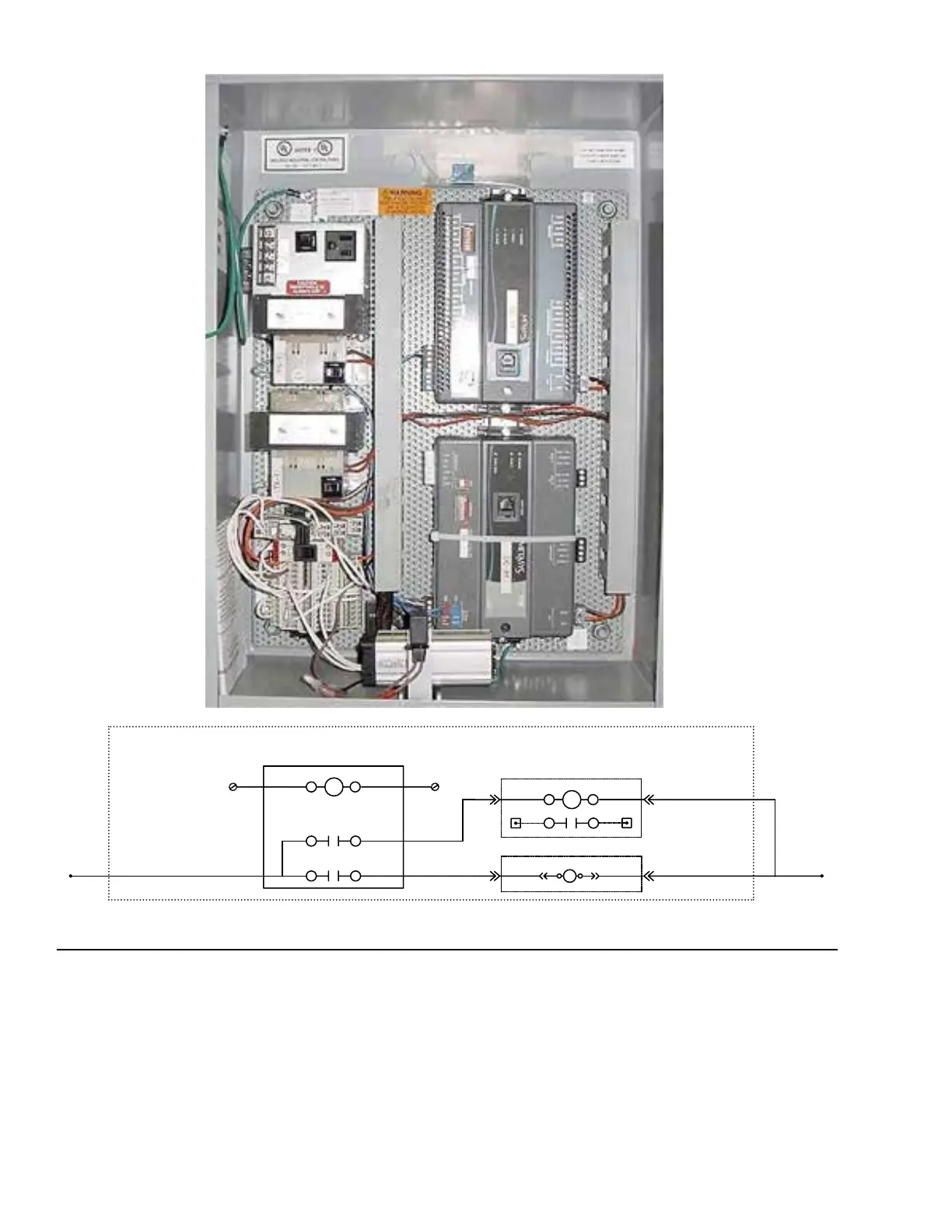
SECTION 5 - WIRING DIAGRAMS
11 14
FROM FEC CONTROLLER OUTPUT
IR-1
R
BLK
OUT1
OCOM1
21 24
RR
R
RUN COMMAND
BO
SF-C
LOCATED IN SUPPLY FAN MOTOR CONTROLLER.
N.O.
R
C
BLK
BLK
BO
OAD-C
LOCATED IN MB/FM
R
SIGNAL COM
DAMPER INTERLOCK RELAY CIRCUIT
A1
A2
6C
LD12500
INSTALLING KIT (IF APPLICABLE)
1. This kit will be required for some of Johnson FEC
control standards (100% outside air).
2. Install relay (P/N 025-39136-001) on the DIN rail
provided in the panel.
FIGURE 95 - OUTSIDE AIR DAMPER KIT (RELAY INSTALLATION)
LD12500a
3. Wire the relay as shown in s shown in Figure 95
on page 92, using the wire called for in the kit.