JOHNSON CONTROLS
37
SECTION 2 - START-UP AND OPERATION
FORM 102.20-OM2
ISSUE DATE: 6/01/2015
2
14. Connect a manometer or other suitable device to
the heat exchanger draft port located on the side
of the AHU near the burner. The expected draft
should read slightly negative about -0.03 inches
WC. The draft port is typically made of 3/4 in
steel pipe and may be plugged. Remove plug and
add a small stop valve and a nipple for a rubber
tube.
15. Install the Honeywell S7800 Test Module, if
available.
16. Connect the signal generator (0-20mA) to ter-
minals in place of modulation control signal (for
2-10VDCsignaladda500Ωresistorinseries).
17. Visually check that the ue (stack) is secure
and connected properly. Typical connections are
shown at the end of these instructions.
18. The burner panel's on/off switch should be off.
19. The system is now ready for start up.
FIGURE 29 - OPEN FUSE DISCONNECTS
LD12903
BURNER
CONTROL
PANEL
FIGURE 30 - SET ID FAN DAMPER
LD12910
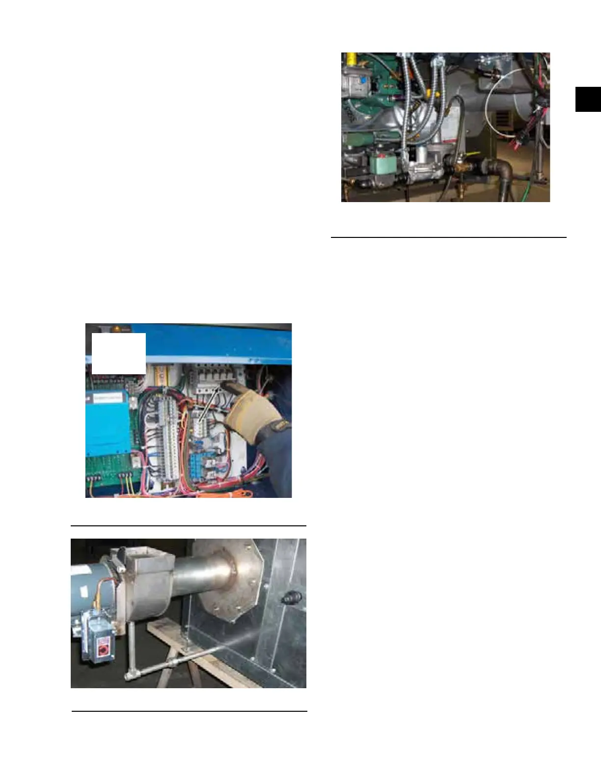
FIGURE 31 - CHECK MAIN GAS SUPPLY
PRESSURE
LD12905
Starting the Burner
1. Prior to starting the burner, the technician must
verify the incoming gas pressure. A minimum
pressure is listed on the burner test report. The
maximum pressure is listed as well.
2. Open the manual gas valves on gas supply and
pilot line.
3. Initiate a call for heat or use jumper to create a
call for heat.
4. Turn the burner panel on/off switch to on.
5. Once there is a call for heat, a 30-second pre-
purge period is initiated to remove any gases from
the heat exchanger. The burner will go through a
second purge before ignition.
6. The burner will automatically go to low re at
start-up.After proof of low re, the burner will
modulateuptohighre,whichmaytake15sec-
onds for a Powerame burner, and 90-180 sec-
onds for the Eclipse burner. After the burner oper-
ates at High Fire use the manometer connected to
the Heat Exchanger Draft Port as shown in Figure
32 on page 38, observe the reading. A pressure
of-0.03inchesWCisexpectedfordraftoverre.
Readings may differ slightly from those shown on
the Burner Test Report.
7. For valid readings before making any adjust-
ments,allowtheburnertoreatleast20minutes
to allow the heat exchanger to rise to the operating
temperature.
8. Observe the gas manifold pressure and compare
to the data on the Burner Test Report under both
highandlowreconditions.