JOHNSON CONTROLS
83
SECTION 4 - SERVICE AND REPAIR
FORM 102.20-OM2
ISSUE DATE: 6/01/2015
4
LD05631
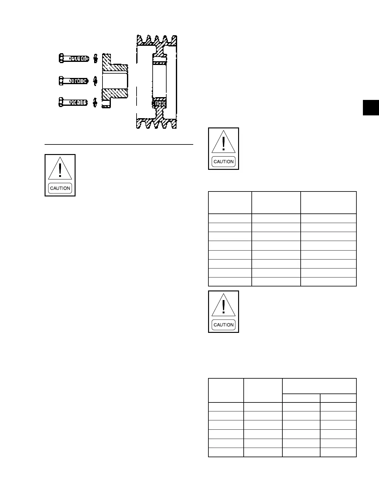
FIGURE 90 - REVERSE MOUNTING
Excessive wedging will split the bushing.
Do not tighten the set screw to standard
torque values at this time.
Do not use the lubricant on the cap screws.
Standard Mounting
1. Install the shaft key. If a key was furnished with
the bushing, use that key.
2. Installthebushingonthecleanshaft,angeend
rst.Ifthebushingwillnotfreelyslideontothe
shaft, insert a screwdriver or similar object into
theange sawcut toact asawedge toopenthe
bushings bore.
3. If using the set screw, tighten it enough to prevent
the bushing from sliding onto the shaft.
4. Slide the sheave into position on the bushing,
aligning the drill holes in the sheave with the
tappedholesinthebushingange.
5. Loosely thread the caps crews with the lock wash-
ers into the assembly.
Reverse Mounting
1. With large end of the out, slide the sheave onto
the shaft as far as possible. Install the shaft key.
2. If a key was furnished with bushing, use that key.
3. Install the bushing onto the shaft so that the ta-
pered end will mate with the sheave.
4. If using the set screw, tighten it enough to prevent
the bushing from sliding onto the shaft.
a. Pull the sheave up onto the bushing, align the
drilled holes in the bushing flange with the
tapped holes in the sheave.
b. Loosely thread the cap screws with lock
washers into the assembly.
Using a torque wrench, tighten all the cap screws even-
ly and progressively in rotation to the torque value as
shown in Table 19 on page 83. There must be a gap
between the bushing flange and sheave hub when in-
stallation is complete.
Do not over torque. Do not attempt to close
the gap between the bushing ange and
the sheave hub.
TABLE 19 - CAP SCREW TORQUE VALUES
TAPERED
BUSHING
SIZE AND
THREAD OF
CAP SCREW
FT-LB TO APPLY
WITH TORQUE
WRENCH
QT 1/4 x 1 9
JA No. 10-24 5
SH-SDS-SD 1/4-20 9
SK 5/16-18 15
SF 3/8-16 30
E 1/2-13 60
F 9/16-12 110
J 5/8-11 135
The tightening force on the screws is mul-
tiplied many times by the wedging action
of the tapered surface. If extreme tight-
ening force is applied, or if a lubricant is
used, bursting pressures will be created in
the hub of the mating part.
5. Tighten all set screws according to the values in
Table 20 on page 83.
TABLE 20 - SET SCREW TORQUE VALUES
SET SCREW
DIAMETER
HEX WRENCH
SIZE ACROSS
FLATS
MIN. RECOMMENDED
TORQUE
IN-LB FT-LBS
1/4 1/8 66 - 85 5.5 - 7.08
5/16 5/32 126 - 164 10.5 - 13.7
3/8 3/16 228 - 296 19.0 - 24.7
7/16 7/32 348 - 452 29.0 - 35.7
1/2 1/4 504 - 655 42.0 - 54.6
5/8 5/16 1104 - 1435 92.0 - 119.6
 Loading...


