JOHNSON CONTROLS
36
FORM 102.20-OM2
ISSUE DATE: 6/01/2015
SECTION 2 - START-UP AND OPERATION
1
1
2
4
3
1
2
3
4
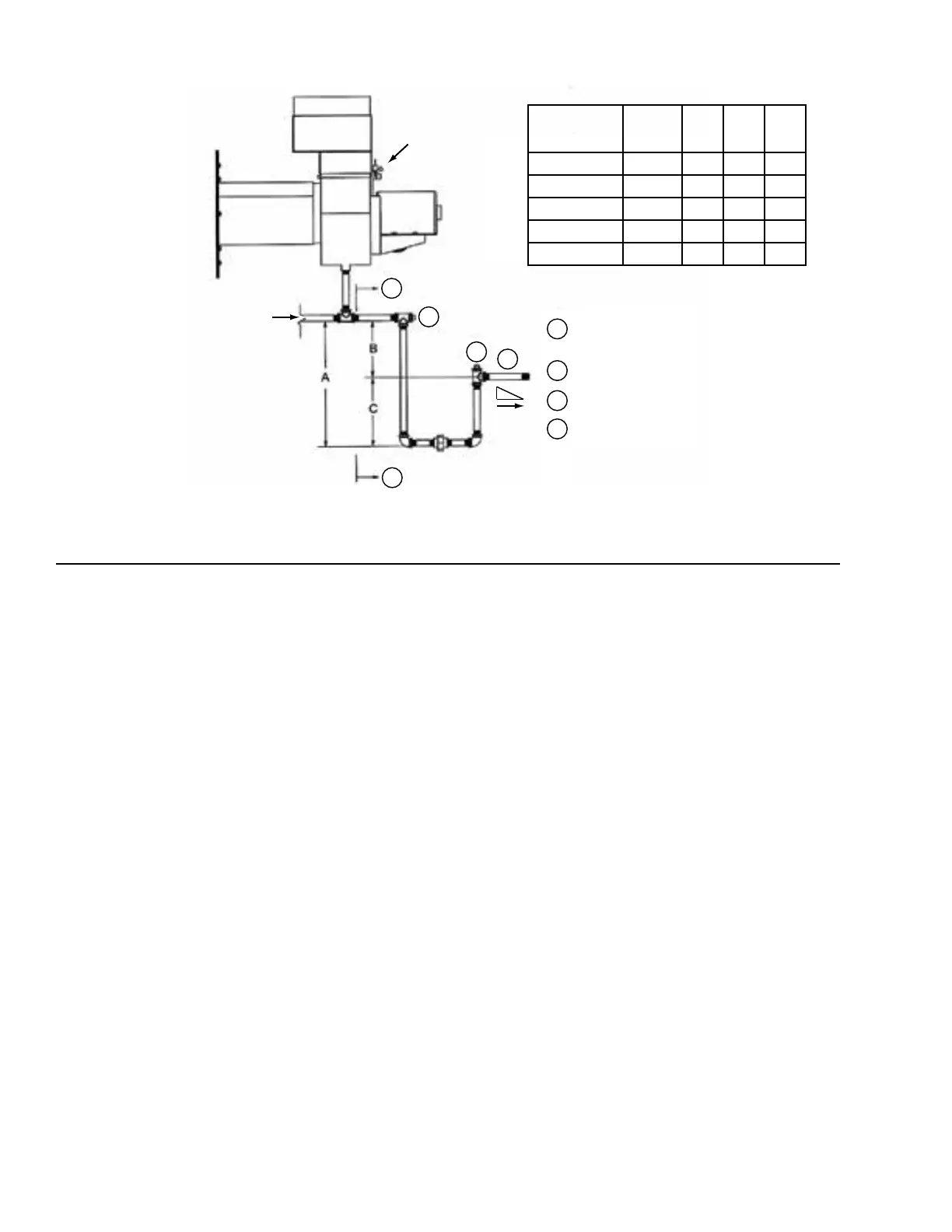
LD12912
FIGURE 28 - GAS FURNACE CONDENSATE DRAIN TRAP
Flow
Burner
Assy
Field Installed Condensate
Drain Piping - By Others
Clean Out
Water Seal Prime/Fill
Pitch 1/4" / Foot
Pitch
ID
Motor
MODEL
DRAIN
NPT
A B C
DF-15 / 25 1/2" 4" 2" 2"
DF-30 / 50 1/2" 8" 4" 4"
DF-60 / 75 1" 8" 4" 4"
DF-85 / 200 1" 12" 6" 6"
DF-225 / 400 1" 16" 8" 8"
Checking the Burner
1. Open the fuse disconnects before working on
burner as shown in Figure 29 on page 37.
2. Check all wire terminations for tightness.
3. Check that the incoming voltage(s) are correct.
Compare the measured voltages to the burner mo-
tor and ID motor nameplates, and the burner test
report. Reset the fuse disconnects.
4. Check for the correct rotation of the three phase
burner and ID motors.
5. Verify that the contractor purged the new gas lines
of air up to the manual valve on the gas train.
6. Open the valves, which were closed for shipping.
Check that all manual valves operate without
leaks.
7. Theue(stack)damperislocatedatthedischarge
of the ID blower and was closed for shipping. Re-
lease the locking mechanism, and set the damper
to match the position indicated by the scribed
markings. Lock it in place as shown in Figure 30
on page 37.
8. Inspect the condensate drain trap to see that it is
large enough.
9. Measure the gas supply pressure coming into the
gas train as shown in Figure 31 on page 37. Gas
pressure can be greater than shown on the burner
test report, but it must be between the min./max.
values listed in Table 7 on page 41.
10. Visually check that the high temperature safe-
ty limit is set for a 200-230°F range. The limit
switch is typically mounted behind the burner
control panel.
11. Connect a 0-15 inch gas pressure gauge or other
suitable instrument to the gas manifold port. The
gas pressure will be measured when running. Re-
fer to Step 4 in Starting the Burner.
12. On Powerame burners, the test port is down-
stream of the main regulator, typically on a stan-
dardteettinginthemaingasline.
13. On Eclipse burners, the test port is located on the
backside of the burner below the spark igniter. A
small valve is provided at this test port.