JOHNSON CONTROLS
55
SECTION 3 - MAINTENANCE
FORM 102.20-OM2
ISSUE DATE: 6/01/2015
3
FAN SEGMENT (SUPPLY, RETURN OR
EXHAUST)
Removing the Fan
If necessary, remove the fans for cleaning. Clean the
fan with detergent or solvent that is environmentally
safe. If water pressure is used, do not direct the water
stream onto the bearing seals.
Forward curved fan wheels are more sus-
ceptible to dirt accumulation than other
wheels. Dirt and debris on fan wheels and
shafts may adversely affect the balance of
the fan assembly.
Refer to the information later in this section to replace
the fan and fan assembly components.
Checking the Fan
Check the following fan parts for damage, wear, loose
parts, and debris:
1. Fan housing, wheel, shaft, frame and bearings
2. Fan base, vibration isolators and optional thrust
restraints
3. Flex connector. Make sure the fan assembly does
notrubtheexmaterial.
4. Drive kit, which consists of belts, sheaves and
sheave bushings. Check for belt tension.
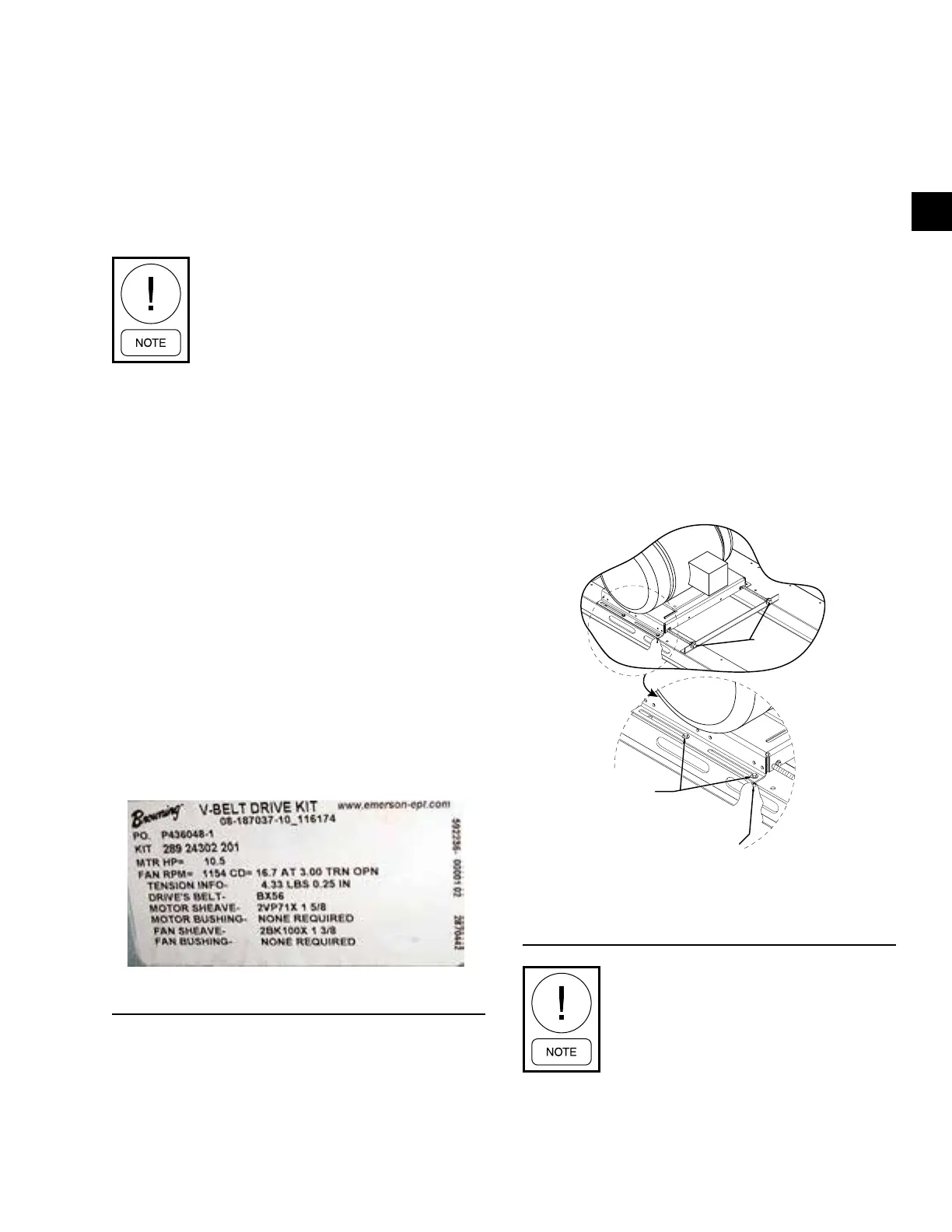
On Solution XT AHUs, the actual data required by de-
sign of each fan assembly is listed on the tag affixed to
the fan housing near the belts, as shown in Figure 43
on page 55.
FIGURE 43 - TYPICAL DRIVE KIT DATA TAG
LD16565
OPERATING ADJUSTABLE MOTOR BASE
Standard
5. Secure the nut with a wrench placed through the
service hole and loosen the bolt. Do this to all four
hold down bolt asssemblies, as shown in Figure
44 on page 55.
6. Make sure the drive bolt assembly threads are
lightly lubricated.
7. Turn both drive bolt assemblies in the same direc-
tion to move motor for belt installation and ten-
sioning.
8. Turn drive bolt assemblies independently to move
motor for sheave/belt alignment.
9. Tighten all four holddown bolt assemblies.
For belt tensioning instruction, refer to Belt Replace-
ment Tensioning and Sheave Alignment for Top Mount
on page 58.
FIGURE 44 - SOLUTION XT ADJUSTABLE MOTOR
BASE
LD09645
Drive Bolt
Assembly
Hold Down Bolt
Assembly
Place Wrench On Nut
Through Service Hole
Procure replacement drive components
locally. A drive label, afxed to the sup-
ply fan, lists the drive specifications.
However, due to possible changes in the
eld, replacement parts must be veried
against installed parts since the installed
parts may not match the label.