JOHNSON CONTROLS
46
FORM 102.20-OM2
ISSUE DATE: 6/01/2015
SECTION 2 - START-UP AND OPERATION
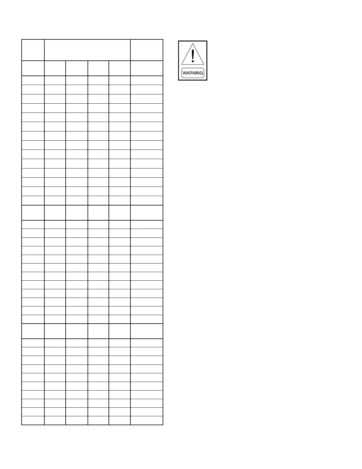
TABLE 9 - BURNER TEMPERATURE RISE (CONT'D)
CFM TEMPERATURE RISE (°F)
INTERNAL
PRESSURE
DROP WC
DF-
175
DF-
200
17,000 95 -- 0.45
18,000 90 -- 0.52
19,000 85 -- 0.57
20,000 81 93 0.63
21,000 77 88 0.7
22,000 74 85 0.76
23,000 71 81 0.82
24,000 68 78 0.9
26,000 62 71 1.05
28,000 58 66 1.25
30,000 54 62 1.4
32,000 51 58 1.6
34,000 48 54 1.8
35,635 45.5 52 2
DF-
225
DF-
250
DF-
275
DF-
300
24,000 87 -- -- -- 0.337
27,000 77 86 92.5 -- 0.427
30,000 69 77 83.3 90.8 0.527
33,000 63 70 75.8 82.5 0.637
36,000 58 64 69.5 75.7 0.758
39,000 53 59 64 70 0.89
42,000 50 55 59.5 65 1.035
45,000 46 51 55.6 60.6 1.185
48,000 43 48 52.1 55.8 1.35
51,000 41 45 50 53.5 1.525
54,000 39 43 47 50.5 1.71
58,475 35 39.5 43.5 47.5 2
DF-
325
DF-
350
DF-
375
DF-
400
31,565 95 -- -- -- 0.4
35,290 85 92 -- -- 0.5
41,755 72 78 83 89 0.7
47,345 64 68 73 78 0.9
52,340 57 62 66 71 1.1
54,665 55 59 64 68 1.2
59,045 51 55 59 63 1.4
63,125 48 51 55 59 1.6
66,950 45 48 52 55 1.8
70,573 42.6 45.9 49.2 52.4 2
Starting the Electric Heater
Rotating parts and electrical shock haz-
ards exist. Lock out and tag out the fan
motor(s) and heat power disconnects be-
fore servicing. FOLLOW THE LATEST
“LOCKOUT TAGOUT” PROCEDURE.
Failure to follow proper safety precau-
tions may result in serious injury or death.
Application Information
1. Follow the procedure given in this instruction to
ndtheminimumairvelocityforsafeoperation
(see Fig. 1). At least this minimum velocity must
be provided at all points over the heater face area.
Failure to meet this requirement may result in se-
rious damage or nuisance thermal cutout tripping.
2. The maximum air inlet temperature for open coil
heaters is 100°F, and for nned tubular heaters,
80°F.
3. Sufcient working space must be provided per
paragraph 110-26 of the National Electrical Code
(NEC).
4. This electric heater is not designed for or intend-
ed to be used for temporary heat prior to system
startup / balancing.
Mechanical Installation
1. All heaters will contain an adjustable airow
switch in the heater control panel. This switch
will be preset to close at a differential pressure of
approximately 0.3" W.C. In all cases the switch
will be connected to a pressure probe positioned
in the airstream. This probe has an arrow stamped
on it that is viewable from inside of the control
panel. When the heater is located upstream of the
fan this arrow will point away from the fan. When
the heater is located on the downstream side of
the fan the arrow will again point away from the
fan or with airow. If it is incorrectly installed,
remove the two screws holding the pressure probe
inplaceandrotate180°andreinstall.Theairow
switch pressure port that is not connected to this
pressure probe will be run to the exterior of the
air handling unit to source a reference differential
pressure. In some situations it may be necessary
to adjust this airow switch setting to allowfor
proper operation. Precautions must be made at
thistimetomakesurethattheairowswitchdoes
notprovideafalseindicationofairow.Failureto
meet this requirement may result in serious dam-
 Loading...


