Chapter 2 Hardware Installation and Connection
NXC Series User’s Guide
30
USB 2.0 Ports
Connect a USB storage device to a USB port on the NXC to archive the NXC system logs or save the NXC
operating system core dump to it.
2.5.3 Front Panel LEDs
This section describes the front panel LEDs.
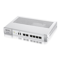
2.5.3.1 NXC2500
The following table describes the LEDs.
Table 6 RJ-45-to-DB-9 Console Cable Color Codes
DB-9 SIGNAL DB-9 PIN# WIRE COLOR RJ45 PIN#
CTS 8 White/Orange 1
DSR/DCD 6+1 Orange 2
RD 2 White/Green 3
GND 5 Blue 4
GND 5 White/Blue 5
TD 3 Green 6
DTR 4 White/Brown 7
RTS 7 Brown 8
Table 7 Front Panel LEDs: NXC2500
LED COLOR STATUS DESCRIPTION
PWR Off The NXC is turned off.
Green On The NXC is turned on.
SYS Green Off The NXC is not ready or has failed.
On The NXC is ready and running.
Blinking The NXC is booting.
Red On There is a hardware component failure. Shut down the device, wait for a few
minutes and then restart the device (see Section 1.6 on page 24). If the LED turns
red again, then please contact your vendor.
Blinking Firmware upgrade is in progress.
P1~P6 Green
(Traffic)
Blinking The NXC is sending or receiving packets to/from an Ethernet network on this
port.
Off The NXC is not sending or receiving packets on this port.
Orange
(Link)
On This port has a successful link to an Ethernet network.
Off There is no connection on this port.

 Loading...