192 CHAPTER 15: MULTICAST OVERVIEW
Ethernet multicast MAC address
When a unicast IP packet is transported in an Ethernet network, the destination
MAC address is the MAC address of the receiver. When a multicast packet is
transported in an Ethernet network, a multicast MAC address is used as the
destination address because the destination is a group with an uncertain number
of members.
As stipulated by IANA, the high-order 24 bits of a multicast MAC address are
0x01005e, while the low-order 23 bits of a MAC address are the low-order 23 bits
of the multicast IP address.
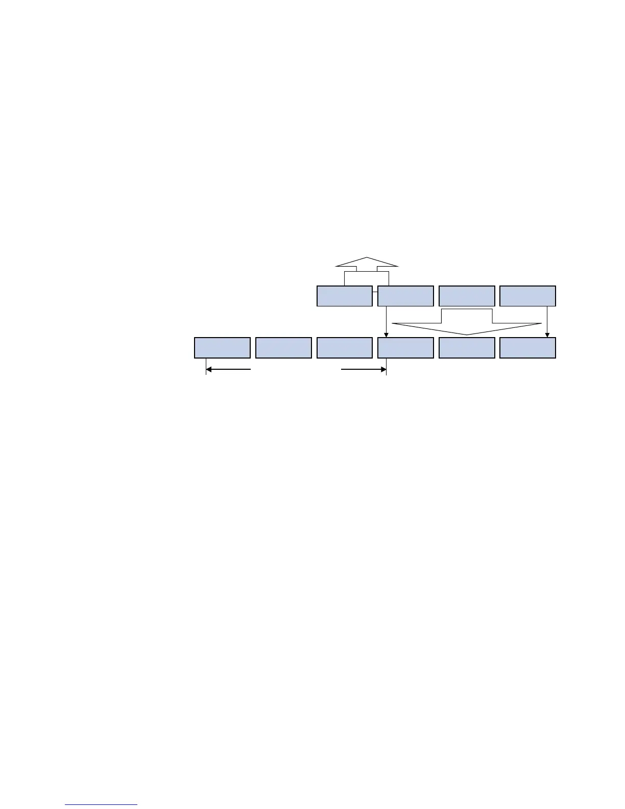
Figure 58 describes the mapping relationship:
Figure 58 Multicast address mapping
The high-order four bits of the IP multicast address are 1110, representing the
multicast ID. Only 23 bits of the remaining 28 bits are mapped to a MAC address.
Thus, five bits of the multicast IP address are lost. As a result, 32 IP multicast
addresses are mapped to the same MAC address.
Multicast Protocols This section provides only general descriptions about applications and functions of
the Layer 2 and Layer 3 multicast protocols in a network. For details about these
protocols, refer to the related chapters of this manual.
Layer 2 multicast protocols
Layer 2 multicast protocols include IGMP Snooping and multicast VLAN. Figure 59
shows where these protocols are in the network.
n
We refer to IP multicast working at the data link layer as Layer 2 multicast and the
corresponding multicast protocols as Layer 2 multicast protocols, which include
IGMP Snooping. The Switch 4210 does support IGMP snooping.
XXXX X
XXXX XXXX XXXX XXXX XXXX XXXX1110 XXXX
0XXX XXXX XXXX XXXX XXXX XXXX0000 0001 0000 0000 0101 1110
32-bit IP address
48-bit MAC address
5 bits lost
25-bit MAC address prefix
ĂĂ
23 bits
mapped