8 PROFIBUS electronics
8.1 Fault protection
The 266 PdP electronic implements the circuitry for the fault
current protection. Whenever a fatal failure occurs and the
current consumption increase over the 20 mA, this circuitry
provides to disconnect the device from the bus, in order to
save the rest of the bus that, otherwise, drops down with all the
other connected devices.
8.2 On-board switches
On the electronic unit (behind the Local Display when installed)
there are 3 switches with the following functionality:
SW 1 – Replace Mode
In UP position (1) it enables the Replacement operation. It must
be used in combination with the SW 2 that selects which part
of the Transmitter is going to be replaced.
SW 2 – Replace Detail
In UP position (1) it selects the Sensor Replacement. The entire
transmitter’s configuration data are kept valid in the electronics
and copied into the memory of the new sensor once it is
connected. In OFF position (0) it selects the Electronics
Replacement. The entire transmitter’s configuration data are
kept valid in the sensor memory and copied into the memory of
the new electronics once it is connected.
SW 3 – Push Buttons Mode
This switch selects the type of operation executed with the
housing push buttons located under the type plate. In UP
position (1) it enables the push buttons for the ranging
operation. In OFF position (0) it enables the push buttons for
the PV bias Set/Reset operations.
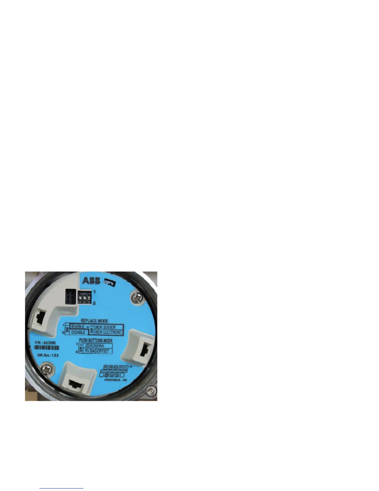
Figure 37: PROFIBUS communication board
8.3 Factory default configuration
The on-board switches are set by default in OFF position (0).
Therefore:
SW 1 – Replace Mode is disabled
SW 2 – Replace Detail on New Electronic but with no effect
since SW 1 is on OFF position.
SW 3 – Push Buttons Mode on OFF position (0). With this
configuration, the external non-intrusive push buttons perform
the PV Bias / Offset functions by default.

 Loading...


