12 Operations
The transmitter makes available to the user some operations
that can be useful during the device life cycle.
These operations are supported and can be executed with the
DTM o EDD based configuration tools, or also by following the
instructions / descriptions below.
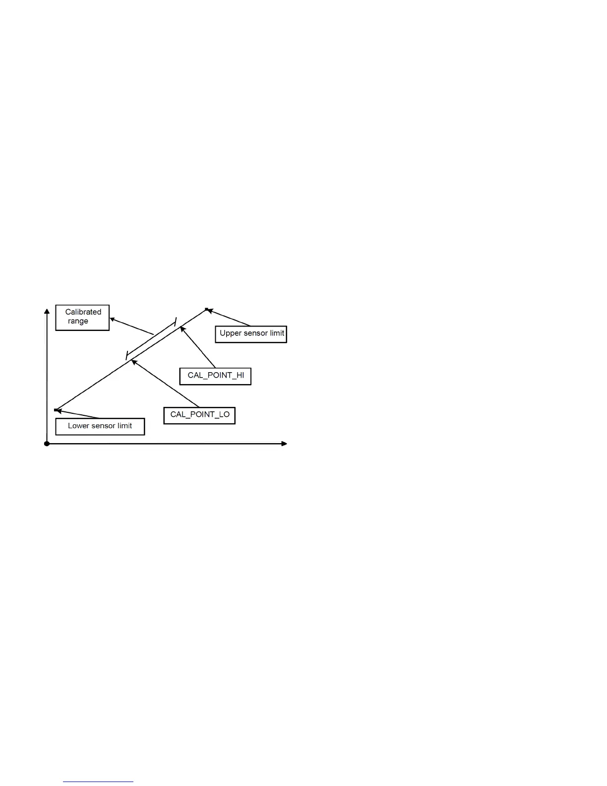
12.1 Sensor trimming / calibration
The scope of the sensor trimming / calibration is to adjust and
make accurate as much as possible the sensor conversion to a
pressure value in digital format.
The sensors of the 266 are calibrated/trimmed in the factory to
the customer‘s specified measuring range therefore it could be
necessary change or correct the sensor calibration later on as
maintenance operation. Two points are necessary to perform a
sensor calibration. Low sensor calibration point (Zero) writing in
PRTB_CAL_POINT_LO and High sensor calibration point
(Span) writing in PRTB_CAL_POINT_HI.
The minimum distance from the two points must be greater
than minimum span PRTB_CAL_MIN_SPAN.
Figure 44: Sensor Trimming / Calibration
12.1.1 P-dP sensor low trimming
With this operation the PRTB_TRIMMED_VALUE is
automatically adjusted, in order to match the real value of the
pressure applied in input, in the low part of the working range.
The following sequence of operations is required:
1. Apply a reference pressure in input using a reference
pressure generator.
2. Select the engineering unit of the measure in the
PRTB_SENSOR_UNIT (Pressure Unit Only)
3. Read the measure produced by the transmitter from the
PRTB_TRIMMED_VALUE.
4. If this value doesn’t match the pressure applied in input,
enter the correct known applied pressure value in the
PRTB_CAL_POINT_LO and write to the transmitter.
This writing executes an internal algorithm that produces the
new correction coefficients.
5. Read again the PRTB_TRIMMED_VALUE and check if its
value matches the applied pressure.
This operation can be executed also with the optional keypad
from the menu “Calibration/P-dP Sensor/Low Trimming”.
12.1.2 P-dP sensor high trimming
With this operation the PRTB_TRIMMED_VALUE is
automatically adjusted, in order to match the real value of the
pressure applied in input, in the high part of the working range.
The following sequence of operations is required:
1. Apply a reference pressure in input using a reference
pressure generator.
2. Select the engineering unit of the measure in the
PRTB_SENSOR_UNIT (Pressure Unit Only)
3. Read the measure produced by the transmitter from the
PRTB_TRIMMED_VALUE.
4. If this value doesn’t match the pressure applied in input,
enter the correct known applied pressure value in the
PRTB_CAL_POINT_HI and write to the transmitter.
This writing executes an internal algorithm that produces the
new correction coefficients.
5. Read again the PRTB_TRIMMED_VALUE and check if its
value matches the applied pressure
This operation can be executed also with the optional keypad
from the menu “Calibration/P-dP Sensor/High Trimming”.
12.1.3 Static pressure low trimming
With this operation the PRTB_STATIC_P_TRIM_VALUE is
automatically adjusted, in order to match the real value of
Static Pressure applied at the transducer in the lower part of
the range. The following sequence of operations is required:
1. Select the engineering unit of the measure in the PRTB_
STATIC_P_SENSOR_UNIT (Pressure Unit Only)
2. Read the Static Pressure value from the
PRTB_STATIC_P_TRIM_VALUE.
3. If this value doesn’t match the known Static Pressure
applied in input at the transducer, enter the correct value
in the PRTB_STATIC_P_CAL_POINT_LO and write to the
transmitter. This writing executes an internal algorithm
that produces the new correction coefficients.
4. Read again the PRTB_STATIC_P_TRIM_VALUE and
check if its value matches the real Static Pressure value.
12.1.4 Static pressure high trimming
(for piezo dP sensor only)
With this operation the PRTB_STATIC_P_TRIM_VALUE is
automatically adjusted, in order to match the real value of
Static Pressure applied at the transducer in the upper part of
the range. The following sequence of operations is required:
1. Select the engineering unit of the measure in the
PRTB_STATIC_P_SENSOR_UNIT (Pressure Unit Only)
2. Read the Static Pressure value from the
PRTB_STATIC_P_TRIM_VALUE.
3. If this value doesn’t match the known Static Pressure
applied in input at the transducer, enter the correct value
in the PRTB_STATIC_P_CAL_POINT_HI and write to the
transmitter. This writing executes an internal algorithm
that produces the new correction coefficients.
4. Read again the PRTB_STATIC_P_TRIM_VALUE and
check if its value matches the real Static Pressure value.

 Loading...


