The cyclic telegram can be formed by minimum 5 byte up to
15 bytes max. Structure of the input cyclic telegram from
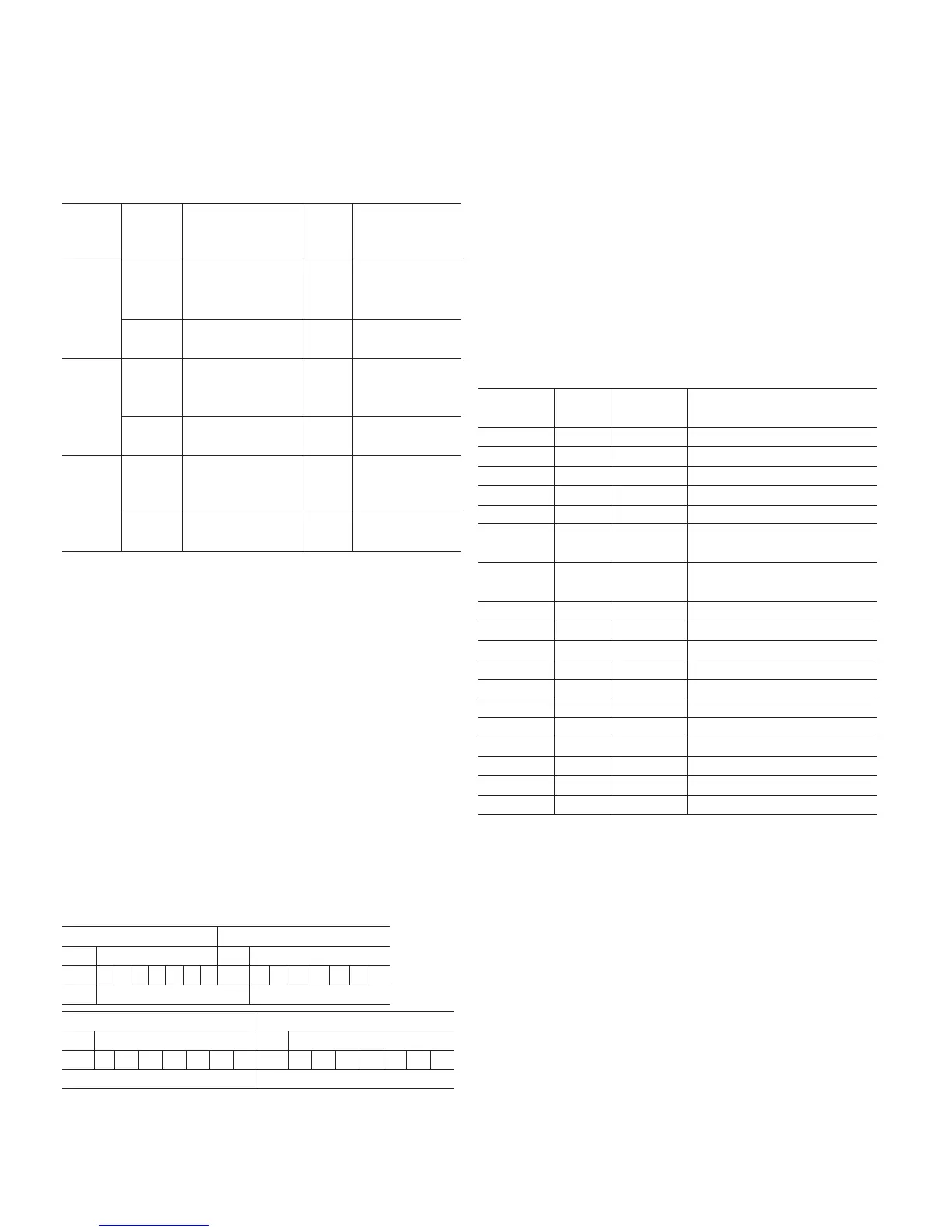
2600T 266 PdP to Class 1 Master in Data_Exchange service.
In this table is reported the max.configuration when all the
three AI blocks output are transmitted to the Class 1 Master.
Different combinations are also possible according the GSD
module selections.
Function
Blocks
Index
input
data
Variables access Data type
AI1_OUT
0, 1, 2, 3
Process Value:
Pressure, Level,
Flow, Volume
Read
32 bits Floating
Point Format
(IEEE 754)
4
Status Byte for
Process Value
Read
See Status Byte
coding
AI2_OUT
5, 6, 7, 8 Static Pressure Read
32 bits Floating
Point Format
(IEEE 754)
9
Status Byte for Static
Pressure
Read
See Status Byte
coding
AI3_OUT
10, 11,
12, 13
Auxiliary Value:
Sensor Temperature,
Pressure
Read
32 bits Floating
Point Format
(IEEE 754)
14
Status Byte for
Auxiliary Value
Read
See Status Byte
coding
11.2.1 Network configuration
When the 266 PdP transmitter has to be used in a profibus
project, the first operation is to import in the Host (Class 1
Master) the GSD file of the device. The manufacturer specific
GSD filename of the 2600T-266 PdP transmitter is AB013450.
GSD The GSD file can be downloaded from the ABB website
www.abb.com. When the GSD file has been imported in the
Host then the transmitter can be used in a network design. In
order to configure a Profibus Node for the 266 PdP: select the
266 PdP from the available GSD files list, assign a valid
Address (1….125) and then select from the GSD file the Module
with the required variables to be transmitted via cylcic telegram
for that specific Node Address.
Cyclic communication
The output of each AI block is 5 bytes. The Variable is 32 bit in
Floating Point format (4 bytes) plus a Status Byte (1 Byte).
Variable structure
The Floating Point format of each variable read by the Class 1
master is as follow:
Byte n Byte n+1
Bit 7 Bit 6 Bit 7 Bit 6
S 2
7
2
6
2
5
2
4
2
3
2
2
2
1
2
0
2
-1
2
-2
2
-3
2
-4
2
-5
2
-6
2
-7
EXPONENT MANTISSA
Byte n+2 Byte n+3
Bit 7 Bit 7
2
-8
2
-9
2
-10
2
-11
2
-12
2
-13
2
-14
2
-15
2
-16
2
-17
2
-18
2
-19
2
-20
2
-21
2
-22
2
-23
MANTISSA MANTISSA
Example:
40 F0 00 00 (hex) = 0100 000 111 000 000 000 000 000 (binary)
Calculation:
Value = (-1) S * 2 (Exponent – 127) * (1 + Mantissa)
Value = (-1) 0 * 2 (129 – 127) * (1 + 2-1 + 2-2 + 2-3)
Value = 1 * 4 * (1 + 0.5 + 0.25 + 0.125) = 7.5
Status byte
The Status byte is the fifth byte of any out value and represents
the Quality of the variable. The 266 PdP supports both the
Classic Status and Condensed Status conditions as allowed by
the Profile 3.02. Depending by which of the two selections is
active, the list of the possible Status in output of the AI blocks
can be the following:
— Classic Status
Binary Code
Decimal
Code
Quality Sub-Status
0000 00xx 0-3 BAD non specific
0000 11xx 12-15 BAD Device Failure
0001 00xx 16-20 BAD Sensor Failure
0001 1111 31 BAD Out of Service
0100 0000 64 UNCERTAIN non specific
0100 0100 68 UNCERTAIN
last usable value (LUV)
– ( FSAFE_TYPE = 1)
0100 1000 72 UNCERTAIN
substitute value
– (FSAFE_TYPE = 0)
0100 1100 76 UNCERTAIN initial value (FSAFE_TYPE = 0)
0101 00xx 80-83 UNCERTAIN sensor conversion not accurate
0101 01xx 84-87 UNCERTAIN engineering unit range violation
0110 00xx 96-99 UNCERTAIN simulated value
1000 0000 128 GOOD_NC ok
1000 0100 132 GOOD_NC Update Event
1000 1010 138 GOOD_NC Active Advisory Alarm high
1000 1110 142 GOOD_NC Active Critical Alarm high
1000 1001 137 GOOD_NC Active Advisory Alarm low
1000 1101 141 GOOD_NC Active Critical Alarm low
1010 0100 164 GOOD_NC Maintenance Required

 Loading...


