128 Program features
To fulfill the insulation requirement, connect a thermistor (and other similar
components) to the drive’s control terminals using any of these alternatives:
• Separate the thermistor from live parts of the motor with double reinforced
insulation.
• Protect all circuits connected to the drive’s digital and analog inputs. Protect
against contact, and insulate from other low voltage circuits with basic insulation
(rated for the same voltage level as the drive’s main circuit).
• Use an external thermistor relay. The relay insulation must be rated for the same
voltage level as the drive’s main circuit.
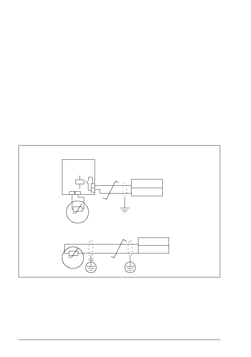
The figure below shows alternate thermistor connections. At the motor end the cable
shield should be grounded through a 10 nF capacitor. If this is not possible, leave the
shield unconnected.
It is also possible to monitor motor temperature by connecting a PTC sensor and
a thermistor relay between the +24 V DC voltage supply offered by the drive and a
digital input. The figure below displays the connection.
For other faults, or for anticipating motor overheating using a model, see Group 30:
Fault functions.
T
Thermistor
relay
MMIO board
DI1…5
+24 V DC
Motor
Par. 3501 = THERM (0) or THERM(1)
Motor
T
10 nF
Thermistor (0)
MMIO board
DI5
+24 VDC