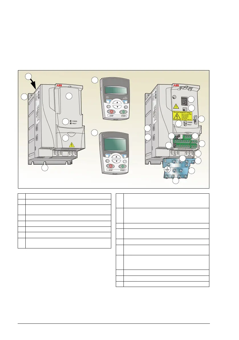
1 Cooling outlet through top cover
2 Mounting holes
3 Panel cover (a) / Basic control panel (b) /
Assistant control panel (c)
4 Terminal cover
5 Panel connection
6 Option connection
7 FlashDrop connection
8 Power OK and Fault LEDs. See section
LEDs on page 381.
9 EMC filter grounding screw (EMC).
Note: The screw is on the front in frame
size R4.
10 Varistor grounding screw (VAR). See
section Protecting the contacts of relay
outputs on page 44.
11 EIA-485 connection
12 Jumper J701 for connecting EIA-485
termination resistor
13 I/O connections
14 Jumper S1 for selecting voltage or current
for analog inputs
15 Input power connection (U1, V1, W1) and
motor connection (U2, V2, W2). (Braking
chopper connection is disabled.)
16 I/O clamping plate
17 Clamping plate
18 Clamps
2
4
3b
3a
3c
5
6
7
8
13
2
11
10
9
8
15
18
18
16
17
1
12
14
Covers on (R2) Covers off (R2)