92 Application macros
Floating point
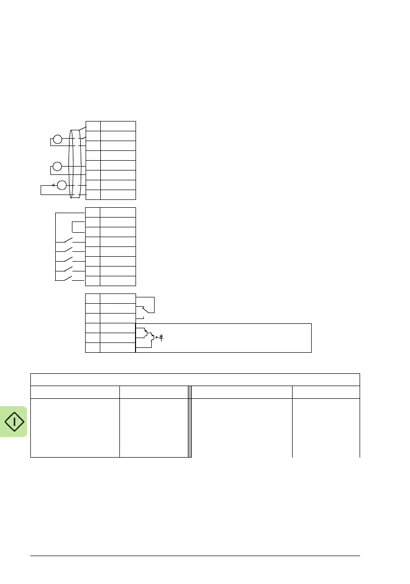
This application macro is for applications where speed reference needs to be
controlled through digital inputs (DI4 & DI5). By activating digital input 4, the speed
reference increases, by activating digital input 5, the speed reference decreases. If
both digital inputs are active or inactive, the reference does not change.
For more information see Default values with different macros on page 279.
Parameters changed relative to HVAC default
Parameter Value
Parameter Value
9902 APPLIC MACRO 10 (FLOATINGPNT) 3416 SIGNAL3 MIN
1103 REF1 SEL 30 (DI4U, 5D)
3418 OUTPUT3 DSP FORM 1 (+/-0.0)
1401 RELAY OUTPUT 1 7 (STARTED)
3419 OUTPUT3 UNIT 0 (%)
1601 RUN ENABLE 2 (DI2)
3420 OUTPUT3 MIN -200.0%
3415 SIGNAL3 PARAM 0105 (TORQUE)
3421 OUTPUT3 MAX 200.0%
1SCR
2AI1
3AGND
410V
5AI2
6AGND
7AO1
8AGND
924V
10 GND
11 DCOM
12 DI1
13 DI2
14 DI3
15 DI4
16 DI5
17 RO1C
18 RO1A
19 RO1B
20 DOSRC
21 DOOUT
22 DOGND
External reference 0(2)…10 V or 0(4)…20 mA
Reference voltage 10 VDC
Output frequency: 0(4)…20 mA
Start/Stop: Activate to start drive
Run permissive: Deactivate to stop drive (P 1601)
Safety interlock1: Deactivate to stop drive (P 1608)
Reference Up: Activate to increase reference
Reference Down: Activate to decrease reference
Relay output 1 (P 1401)
Default operation: Started =>17 connected to 19
Digital output, max. 100 mA (P 1805)
No fault [Fault(-1)] =>20 connected to 22
X1A
Analog input circuit common
PID feedback: 0(2)…10 V or 0(4)…20 mA
Analog output circuit common
Auxiliary voltage output +24 VDC
Auxiliary voltage output common
Digital input common for all
Signal cable shield (screen)
Analog input circuit common
+
mA
+
X1B