296 Fieldbus control
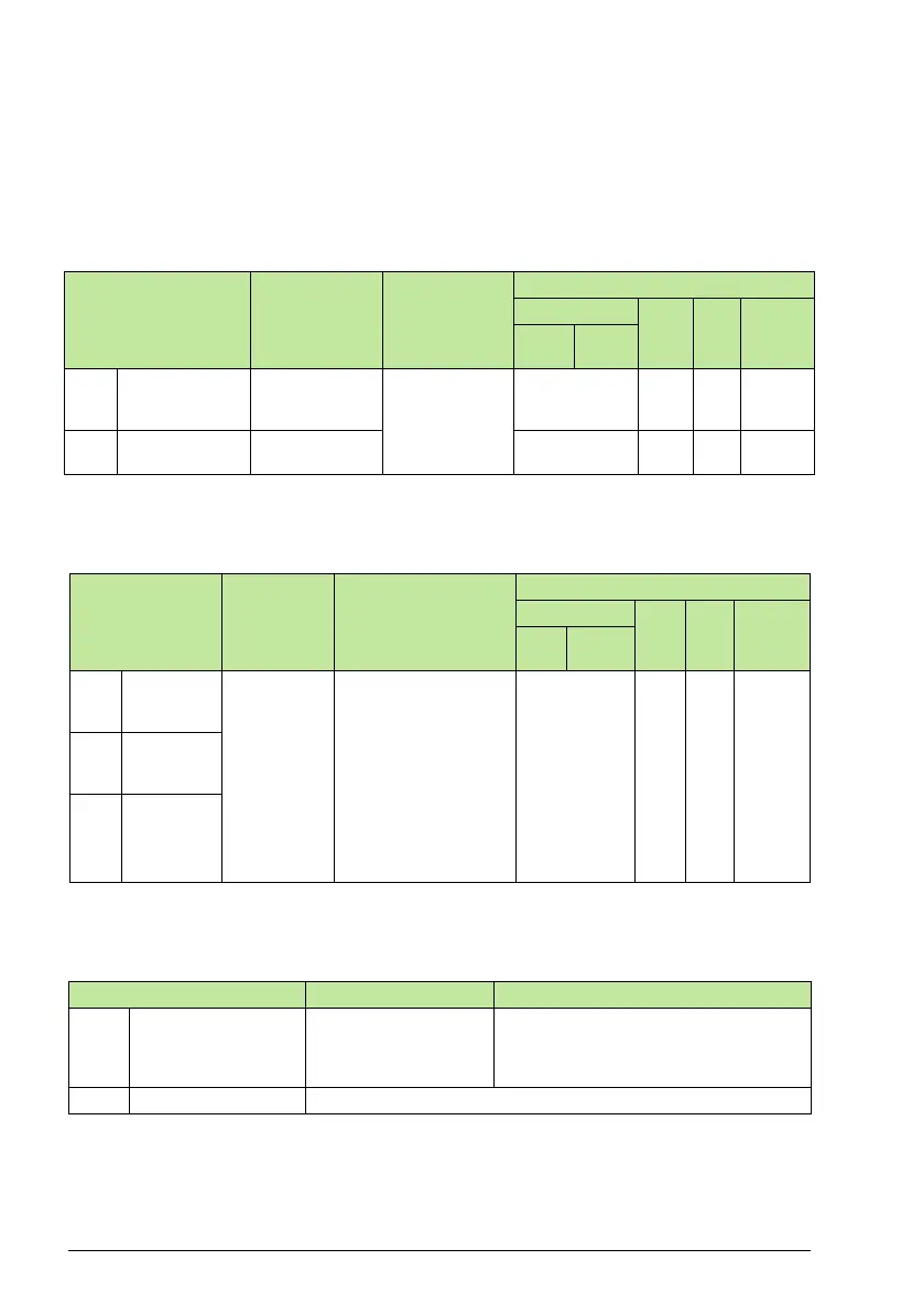
Analog output control
Using the fieldbus for analog output control requires:
• Drive parameter values set as defined below.
• Fieldbus controller supplied reference word(s) in the appropriate location. (The
location is defined by the Protocol Reference, which is protocol dependent.)
PID control setpoint source
Use the following settings to select the fieldbus as the setpoint source for PID loops:
Communication fault
When using fieldbus control, specify the drive’s action if serial communication is lost.
Drive Parameter Value Setting
Protocol Reference
Modbus
N2 FLN BACnet
abb
drv
dcu
profile
1501 AO1
CONTENT SEL
135
(COMM VALUE
1)
Analog Output
1 controlled by
writing to
parameter
0135.
––––
0135 COMM VALUE
1
– 40135 AO14 46 AO0
Drive Parameter Value Setting
Protocol Reference
Modbus
N2 FLN BACnet
abb
drv
dcu
profile
4010 SET
POINT
SEL (Set 1)
8 (COMM
VALUE 1)
9 (COMM +
AI1)
10
(COMM*AI1)
Setpoint is either:
Input Reference 2
(+/-/* AI1). Control
requires parameter
1106 value = comm.
Process PID setpoint.
Control requires
parameter 1106 value
= pid1 out and
parameter 4010 value
= comm.
40003 AO2 61 AV17
4110 SET
POINT
SEL (Set 2)
4210 SET
POINT
SEL
(Ext/Trim)
Drive Parameter Value Description
3018 COMM FAULT FUNC 0 (NOT SEL))
1 (FAULT)
2 (CONST SP7)
3 (LAST SPEED)
Set for appropriate drive response.
3019 COMM FAULT TIME Set time delay before acting on a communication loss.