166 Actual signals and parameters
Analog Input Reference Correction
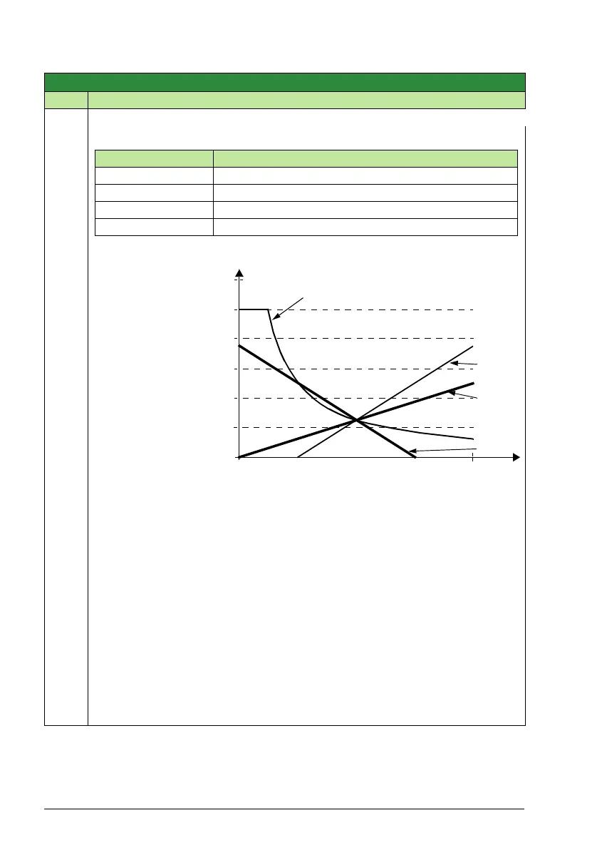
Parameter values 9, 10, and 14…17 use the formula in the following table.
Where:
• C = Main Reference
value
(= COMM for values
9, 10 and
= 1 for values
14…17).
• B = Correcting
reference
(= AI1 for values 9,
10 and
= AI2 for values
14…17).
Example:
The figure shows the
reference source
curves for value
settings 9, 10, and 14…17, where:
•C = 25%.
• Parameter 4012 SETPOINT MIN = 0.
• Parameter 4013 SETPOINT MAX = 0.
• B varies along the horizontal axis.
REF1 SELECT
20 = KEYPAD(RNC) – Defines the control panel as the reference source. A Stop
command resets the reference to zero (R stands for reset.). Changing the control
source (EXT1 to EXT2, EXT2 to EXT1) does not copy the reference.
21 = KEYPAD(NC) – Defines the control panel as the reference source. A Stop
command does not reset the reference to zero. The reference is stored. Changing
the control source (EXT1 to EXT2, EXT2 to EXT1) does not copy the reference.
30 = DI4U,5D – See selection DI3U,4D.
31 = DI4U,5D(NC) – See selection DI3U,4D(NC).
32 = FREQ INPUT – Frequency input.
Group 11: Reference select
Code Description Range Resolution Default S
Value setting Calculation of the AI reference
C + B C value + (B value - 50% of reference value)
C * B C value * (B value / 50% of reference value)
C - B (C value + 50% of reference value) - B value
C / B (C value * 50% of reference value) / B value
120
100
80
60
40
20
0
0
100%
9, 14 (+)
16 (-)
0, 15 (*)
17 (/)
B