(CW xxxx x1*xx xxxx x110)
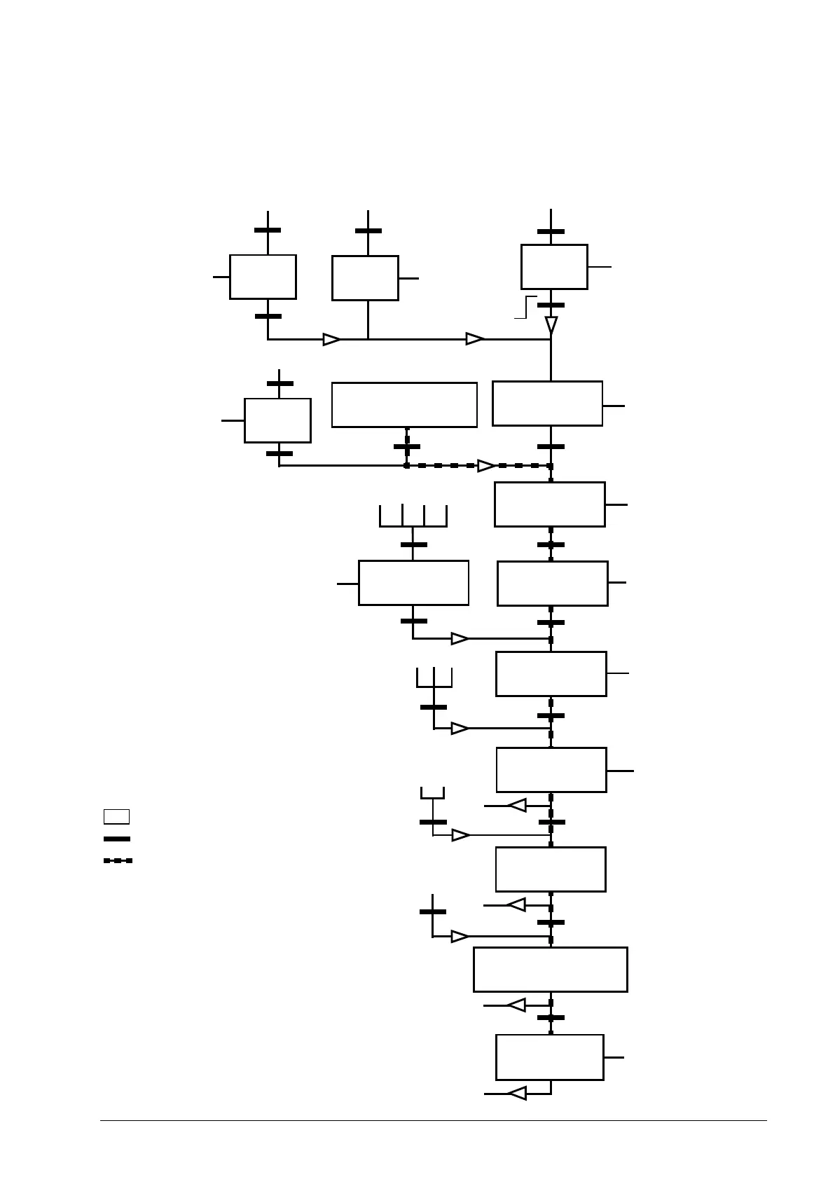
INPUT POWER OFF
Power ON (CW Bit0=0)
(SW Bit6=1)
(SW Bit0=0)
From any state
n(f)=0 / I=0
OFF1 (CW Bit0=0)
ACD
(CW Bit3 =0)
(SW Bit2 =0)
(SW Bit0=1)
(CW= xxxx x1*xx xxxx x111)
(SW Bit1=1)
(CW Bit3=1 and
(CW Bit4=0)*
n(f)=0 / I=0
From any state
SWITCH-ON
INHIBITED
NOT READY
TO SWITCH ON
OPERATION
INHIBITED
READY TO
SWITCH ON
READY TO
OPERATE
RFG OUTPUT
ENABLED*
C* D*
From any state
Emergency Off
OFF2 (CW Bit 1=0)
(SW Bit 4=0)
OFF2
ACTIVE
From any state
Fault
(SW Bit3=1)
FAULT
(CW Bit7=1)**
(SW Bit5=0)
Emergency Stop
OFF3 (CW Bit2=0)
SW Bit12=1)
RFG: ACCELERATOR
ENABLED
(CW=xxxx x1*xx xx11* 1111
(CW Bit6=0)
C
(CW=xxxx x1*xx x111* 1111
(SW Bit8=1)
D
B*
D
OPERATING
OFF3
ACTIVE
(SW Bit2=1)
OPERATION
ENABLED
(CW=xxxx x1*xx xxx1* 1111
A
(CW Bit5=0)
CD
B*
B*
(SW Bit1=0)
OFF1
ACTIVE
OPERATION INHIBITED
ie Bit4=1)*
ie Bit5=1)
ie Bit6=1)
State
State change
Path described in example
CW = Control word
SW = Status word
RFG = Ramp function generator
I = Par. 0104 CURRENT
f = Par. 0103 OUTPUT FREQ
n = Speed
* Supported only by ABB DRV FULL
profile.
** State transition also occurs if the fault
is reset from any other source (eg digital
input).

 Loading...


