50 Electrical installation
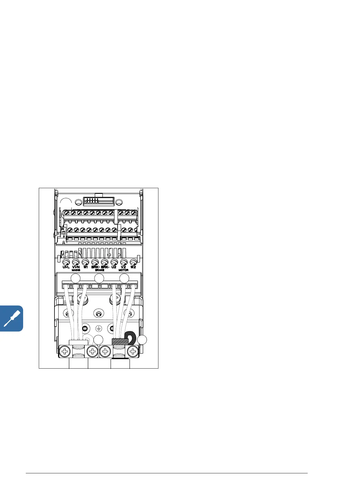
Connection procedure
1. Fasten the grounding conductor (PE) of the input power cable under the
grounding clamp. Connect the phase conductors to the U1, V1 and W1 terminals.
Use a tightening torque of 0.8 N·m (7 lbf·in) for frame sizes R0…R2, 1.7 N·m
(15 lbf·in) for R3 and 2.5 N·m (22 lbf·in) for R4.
2. Strip the motor cable and twist the shield to form as short a pigtail as possible.
Fasten the twisted shield under the grounding clamp. Connect the phase
conductors to the U2, V2 and W2 terminals. Use a tightening torque of 0.8 N·m
(7 lbf·in) for frame sizes R0…R2, 1.7 N·m (15 lbf·in) for R3 and 2.5 N·m (22 lbf·in)
for R4.
3. Connect the optional brake resistor to the BRK+ and BRK- terminals with a
shielded cable using the same procedure as for the motor cable in the previous
step.
4. Secure the cables outside the drive mechanically.