Electrical installation 53
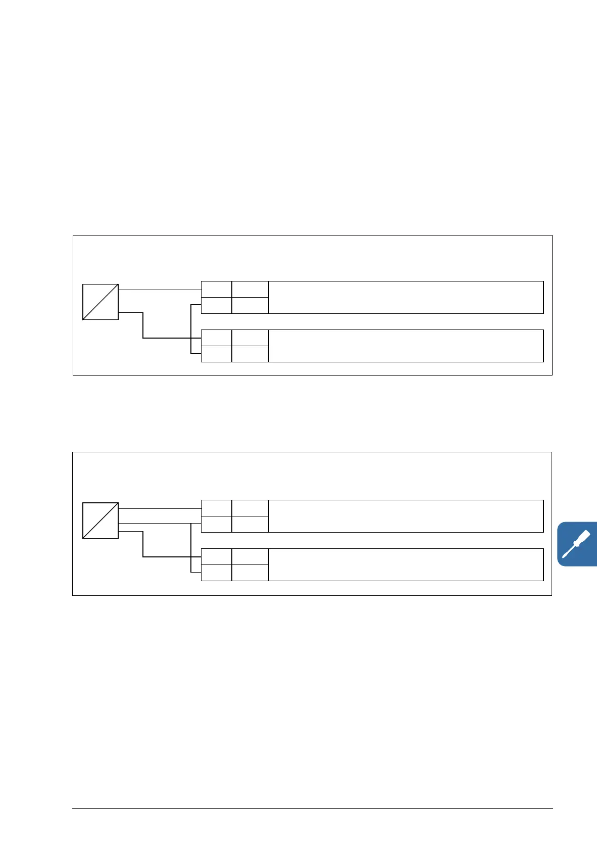
Connection examples of two-wire and three-wire sensors
Hand/Auto, PID control, and Torque control macros (see section Application macros,
pages 116, 117 and 118, respectively) use analog input 2 (AI2). The macro wiring
diagrams on these pages use an externally powered sensor (connections not shown).
The figures below give examples of connections using a two-wire or three-wire
sensor/transmitter supplied by the drive auxiliary voltage output.
Note: Maximum capability of the auxiliary 24 V (200 mA) output must not be
exceeded.
Note: The sensor is supplied through its current output and the drive feeds the supply
voltage (+24 V). Thus the output signal must be 4…20 mA, not 0…20 mA.
X1A
5 AI2 Process actual value measurement or reference,
0(4)…20 mA, R
in
= 100 ohm
6GND
…
9 +24V Auxiliary voltage output, non-isolated,
+24VDC, max. 200mA
10 GND
4…20 mA
Two-wire sensor/transmitter
+
-
P
I
X1A
5 AI2 Process actual value measurement or reference,
0(4)…20 mA, R
in
= 100 ohm
6GND
…
9 +24V Auxiliary voltage output, non-isolated,
+24VDC, max. 200mA
10 GND
(0)4…20 mA
Three-wire sensor/transmitter
+
-
OUT
P
I