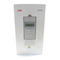
Converter unit hardware
■
Cabinet layout – Frame R7i converter module
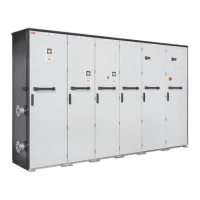
This figure shows an example converter unit cubicle.
A B C
1
2
3
5
4
6
7
8
9
15
12
13
10
16
17
14
18
16
17
11
DescriptionItem desig-
nation
Sym-
bol
Door closed-A
Door open-B
Door open and shrouds removed-C
DC switch-disconnector handle (with option +F286)Q11.11
Charging switch handle (with option +F286)Q10.12
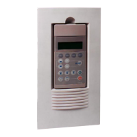
Control panelA493
Door lights:P11.14
• Charging OK [P11.1] (green)
• DC/DC converter disconnected [P12.1] (white)
• Load disconnected [P13.1] (white).
P12.1
P13.1
Input DC fuses (DC bus side)F11.115
F11.12
Charging switch shaft (with option +F286)Q10.16
20 Operation principle and hardware description
 Loading...
