Overview of the control connections of the UCU control
unit
This diagram shows the control connections and interfaces of the UCU control unit.
Control panel7Analog and digital I/O extension modules and
fieldbus communication modules can be in-
serted into slots 1, 2 and 3.
1
2
3
Fiber optic links to power modules (inverter,
supply, brake or converter)
8Memory unit4
Ethernet ports9Slot 4 for RDCO module5
Safety option interface. Reserved for future
use.
10Terminal blocks6
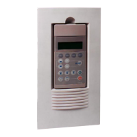
Converter unit control devices
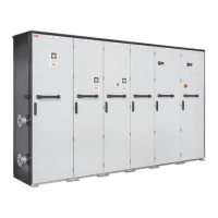
The figure shows an example of the door control devices of the DC/DC converter. The
selection and exact location of control devices varies in different deliveries.
Operation principle and hardware description 31
 Loading...
