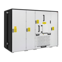
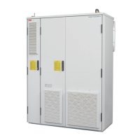
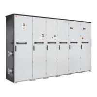
DC switch-disconnector (option +F286)1
Charging switch (option +F286)2
Charging OK indicator, green (option +F286)3
DC/DC converter disconnected indicator, white (option +F286)4
Load disconnected indicator, white5
ACS-AP-W control panel (option +J400)6
■
DC switch-disconnector
The DC switch-disconnector [Q11] is optional (option +F286). The DC
switch-disconnector has an operating handle on the cabinet door. A converter unit
with a DC switch-disconnector also has a charging circuit including a charging switch
on the door.
The DC switch-disconnector allows the isolation of the unit from the DC bus. Before
the unit is connected to the DC bus, the capacitors of the converter modules must be
charged through a charging circuit.
■
Charging switch
A converter unit with a DC switch-disconnector ([Q11], option +F286) also has a charging
circuit and a charging switch [Q10] on the cubicle door. Before closing the DC
switch-disconnector, close the charging switch. After the precharging is completed,
the Charging OK indicator [P11] (green) on the cabinet door comes on, and you can
close the DC switch-disconnector [Q11], and open the charging switch.
■
Door lights
The load disconnected indicator ([P13], white) is always installed on the cabinet door.
This indicator shows the state of the energy storage disconnecting device
(user-defined).
The charging OK indicator ([P11], green) and DC/DC converter disconnected indicator
([P12], white) are installed when the converter has the DC switch-disconnector (option
+F286).
32 Operation principle and hardware description
 Loading...
