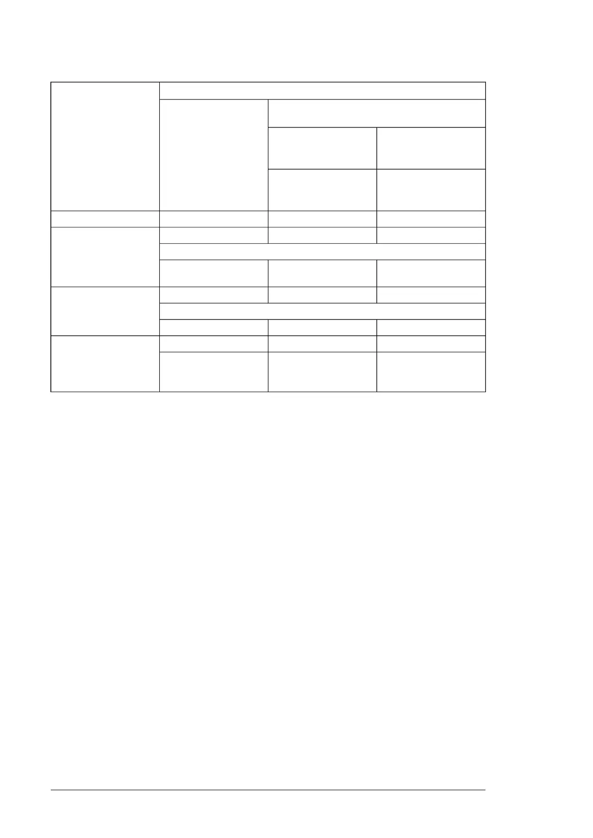
Requirement forNominal AC supply
voltage
ABB du/dt and common mode filters, insulated N-
end motor bearings
Motor insulation system
100 kW < P
N
< 350 kW or
IEC 315 < frame size <
IEC 400
P
N
< 100 kW or frame
size < IEC 315
134 hp < P
N
< 469 hp or
NEMA 500 < frame size <
NEMA 580
P
N
< 134 hp or frame size
< NEMA 500
+ N or CMF+ N or CMF
Standard: Û
LL
= 1300 VU
N
≤ 500 V
+ N + du/dt + CMF+ du/dt + (N or CMF)Standard: Û
LL
= 1300 V420 V < U
N
< 500 V
or
+ N or CMF+ N or CMF
Reinforced: Û
LL
= 1600 V,
0.2 microsecond rise time
+ N + du/dt + CMF+ du/dt + (N or CMF)Reinforced: Û
LL
= 1600 V500 V < U
N
≤ 600 V
or
+ N + CMF+ N or CMF
Reinforced: Û
LL
= 1800 V
+ N + du/dt + CMF+ N + du/dtReinforced: Û
LL
= 1800 V600 V < U
N
≤ 690 V
+ N + CMF+ N + CMF
Reinforced: Û
LL
= 2000 V,
0.3 microsecond rise
time
1)
1)
If the intermediate DC circuit voltage of the drive is increased from the nominal level due to long term resistor braking
cycles, check with the motor manufacturer if additional output filters are needed in the applied drive operation range.
Additional data for calculating the rise time and the peak line-to-line voltage
The diagrams below show the relative peak line-to-line voltage and rate of change of voltage
as a function of the motor cable length. If you need to calculate the actual peak voltage and
voltage rise time considering the actual cable length, proceed as follows:
•
Peak line-to line voltage: Read the relative Û
LL
/U
N
value from the diagram below and
multiply it by the nominal supply voltage (U
N
).
•
Voltage rise time: Read the relative values Û
LL
/U
N
and (du/dt)/U
N
from the diagram
below. Multiply the values by the nominal supply voltage (U
N
) and substitute into equation
t = 0.8 · Û
LL
/(du/dt).
76 Guidelines for planning the electrical installation

 Loading...


