■ Power cable connection diagram
INPUT
OUTPUT
U1
V1
W1
3 ~
M
(PE) PE (PE)
3
4
5
6
7
9
L1
L2 L3
L1
L2
L3
1
2a 2b
PE
L1/
U1 V1
L2/ L3/
W1
UDC- UDC+
T1/
U2
T2/
V2
T3/
W2
PE
8
10
11
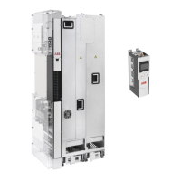
ACS880-34
For alternatives, see Guidelines for planning the electrical installation (page 71). In the installing
example of this chapter, the disconnecting device is not in the same cubicle with the drive module.
1
If a shielded cable is used (not required but recommended) and the conductivity of the shield is <
50% of the conductivity of the phase conductor, use a separate PE cable (2a) or a cable with a
grounding conductor (2b)
2
ABB recommends 360-degree grounding at the cabinet entry if a shielded cable is used. Ground
the other end of the input cable shield or PE conductor at the distribution board.
3
ABB recommends 360-degree grounding at the cabinet entry4
Electrical installation 99
 Loading...
