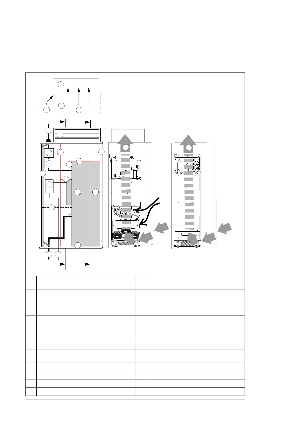
Layout example, door open (option +0B051)
This diagram shows a layout example for drive modules with no IP20 shrouds (option
+0B051) or no cabling panels (option +H381 not included).
PE
T3/W2
T2/V2
T1/U2
1
4
5
6
7
9
3
2a
2a
13
14
10
11
3
2d
2e
2e
L1/U1
L2/V1
L3/W1
2b
2c
14
12
A
A
A – A
15
B– B
16
B
B
8
Motor cable including the protective ground con-
ductor of the drive module
9Supporting frame of the cabinet1
Drive module control unit10
Vertical (2a, 2b) and horizontal (2c, 2d) air baffles
that separate the cool and hot areas (leak-proof
lead-throughs). See section Preventing the recir-
culation of hot air (page 56).
2
External control cables11
Optional air baffle that is needed when there is
no fan on the lower part of the cabinet door. See
section Preventing the recirculation of hot
air (page 56).
2e
Grounding screws12Cabinet grounding busbar (PE)3
Alternative to grounding screws (12)13Input power cable including the protective ground
conductor (PE) of the drive
4
Air flow to the roof14Disconnector and fuses5
Air flow through the drive module15Contactor6
Air flow through the LCL filter16Drive module7
--LCL filter module8
54 Guidelines for planning the mechanical installation

 Loading...


