SHB_U14 Chapter 6: Component Interchange 6-11
Change IR module and Sensor-CPU circuit boards
Removing the circuit
board
To remove the circuit boards, proceed as follows:
Step Action
1 Turn off the analyzer power supply.
2 Open the large door on the system housing.
3 Remove all cable connections from the circuit boards.
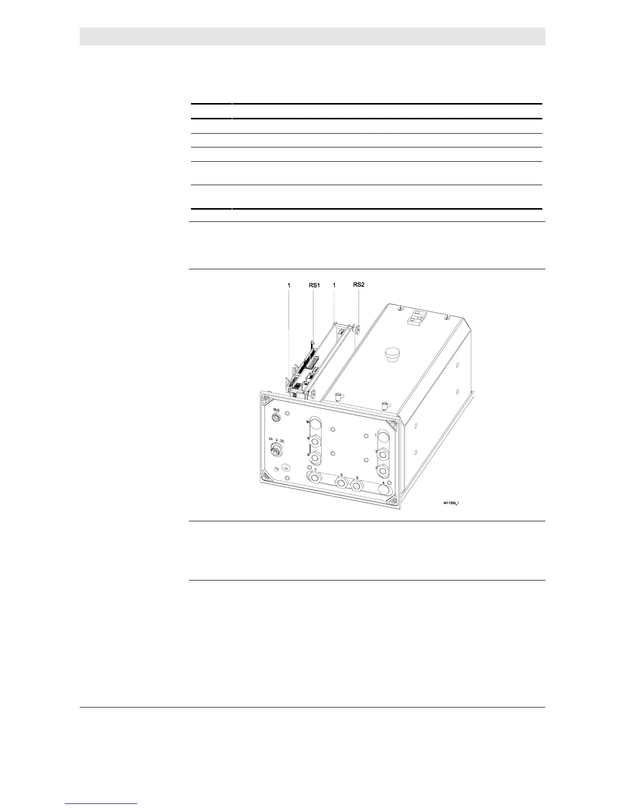
4 Loosen the two knurled nuts (RS1 and RS2) and remove the IR module
and Sensor-CPU board from the support.
5 Remove the four attaching screws (1) and carefully remove the IR
module circuit board from the Sensor-CPU board connector.
Installing the circuit
board
Essentially the installation process is the reverse of the removal process.
Figure 6-11
Analyzer module view
Caution!
The Sensor-CPU circuit board contains the flash EPROM with the module
firmware and the EEPROM with module-specific data.
 Loading...


