II K 4-50
Overview of Software
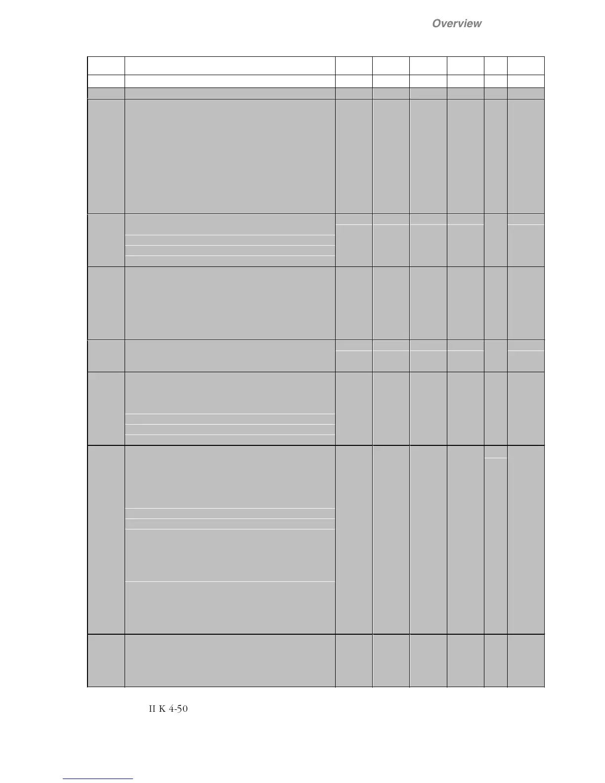
ParNo. Parameter name and significance Min Max Default Unit (1)
custom.
setting
Grp 2 Operation Mode (continued)
Long Parameter Menu
2.07 Comm Fault Mode
Selection of the desired operating response to a
communication failure:
0 = Ramp
Motor is decelerated in accord. to a ramp (5.10)
1 = Torque Lim
Motor is decelerated in accord. to the torque limit
2 = Coast
fault message and shutdown of drive
Response time of deceleration by Ramp or Torque
depends on optimization of speed regulator.
0 2 0 Text
2.08 Comm Fault Time
Tolerance time for fault messages in the case of
communication faults. Time between two successive
messages. If (2.08) = 0.00 s ignore, and continue
with ongoing operation
0.00 10.00 5.00 s
x
2.09 Start Mode
Selection of the desired operating response to a
start command, while drive is still rotating, braking
or coasting
0 = Start From 0: wait until motor has reached zero
speed, then re-start
1 = Flying start: Start with the motor actual speed
0 1 1 Text
x
2.10 DDCS Node Addr
Internal DDCS address between DCS400 and the
field bus adapter.
1 254 1 integer
x
2.11 DDCS Baud Rate
Transmission speed between DCS400 and field bus
adapter.
0 = 8 Mbaud
1 = 4 Mbaud
2 = 2 Mbaud
3 = 1 Mbaud
0 3 1 integer
x
2.12 PTC Mode
The response of the drive when the thermistor trips
is selectable:
0 = Disabled no PTC evaluation
1 = Alarm generates
Alarm A05
only
2 = Fault generates
Fault
F08
and switches
the drive off.
A thermistor in the motor (PTC element) can be
evaluated via the analog input
AI2
in DCS400.
Thermistor connection to
X2:3
and
X2:4.
Connect
X2:4
with
X2:5 (0V).
Insert the jumper
S1:5-6
(22k to 10V).
If PTC is allocated to
AI2
this input will not be
available to other functions any more. If
AI2
is
parameterized as a reference source (macro 1, 2, 4,
5, 7), the Alarm
Parameter Conflict (A16)
will be
generated
.
Then set parameter
Torque Ref Sel
(3.15) = Const Zero
.
0 2 0 Text
x
2.13 Fan Delay
Adjustable time for signal „
Fan On
“. Will be started
when the drive is switched off (ON=0). If motor or
DCS400 is overheated, Fan Delay will be started
after cooling.
0 1200 0 s