Start-up 51
Parameter setting examples – ACS850
Speed control using the CiA 402 velocity mode (vl)
This example shows how to configure a speed control application
that uses the velocity mode (vl) of the CiA 402 profile.
When configuring the master, you need to map the following
objects to the transmit and receive PDOs. For an example, see
section Mapping objects required for controlling the drive on
page 66.
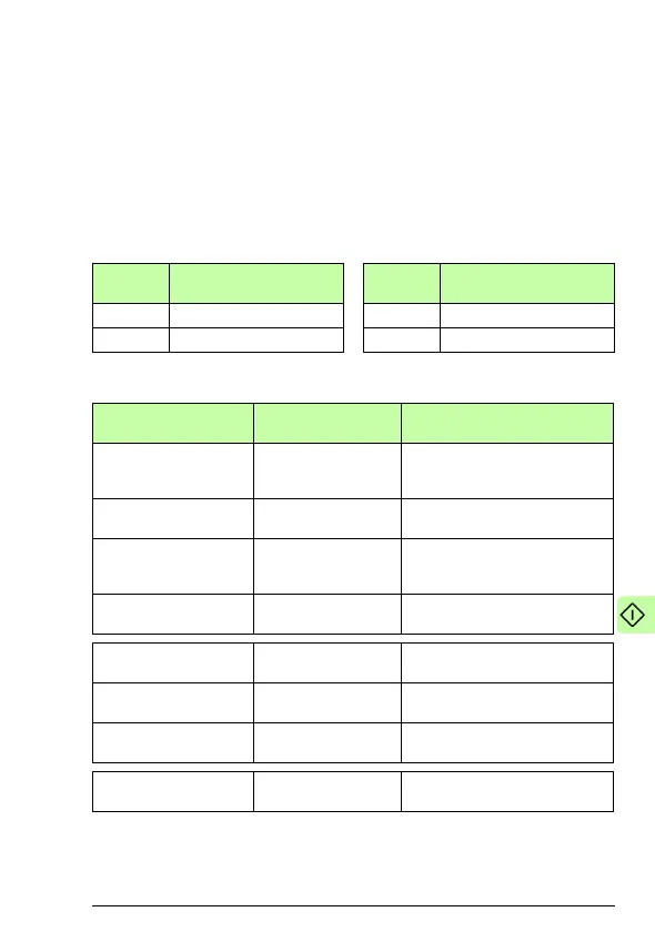
The table below gives the recommended drive parameter settings.
CANopen
object
Output data CANopen
object
Input data
0x6040 Control word 0x6041 Status word
0x6042 Target velocity 0x6044 Vl control effort
Drive parameter Setting for ACS850
drives
Description
50.01 FBA enable Enable Enables communication between
the drive and the fieldbus adapter
module.
50.02 Comm loss func Fault
2)
Enables fieldbus communication
fault monitoring.
50.03 Comm loss t out 3.0 s
2)
Defines the fieldbus
communication break supervision
time.
50.04 FBA ref1 modesel Speed Selects the fieldbus reference 1
scaling.
51.01 FBA type 136 = ETH Pwrlink
1)
Displays the type of the fieldbus
adapter module.
51.02 FBA par2
(PROFILE)
0 (= CiA 402) Selects the CANopen device
profile CiA 402.
51.03 FBA par3
(NODE ID)
3
2)
Defines the address of the
device.
51.27 FBA par refresh Refresh Validates the FEPL configuration
parameter settings.
 Loading...


