InfoAction
Art. no. is specified in Required
equipment on page 294.
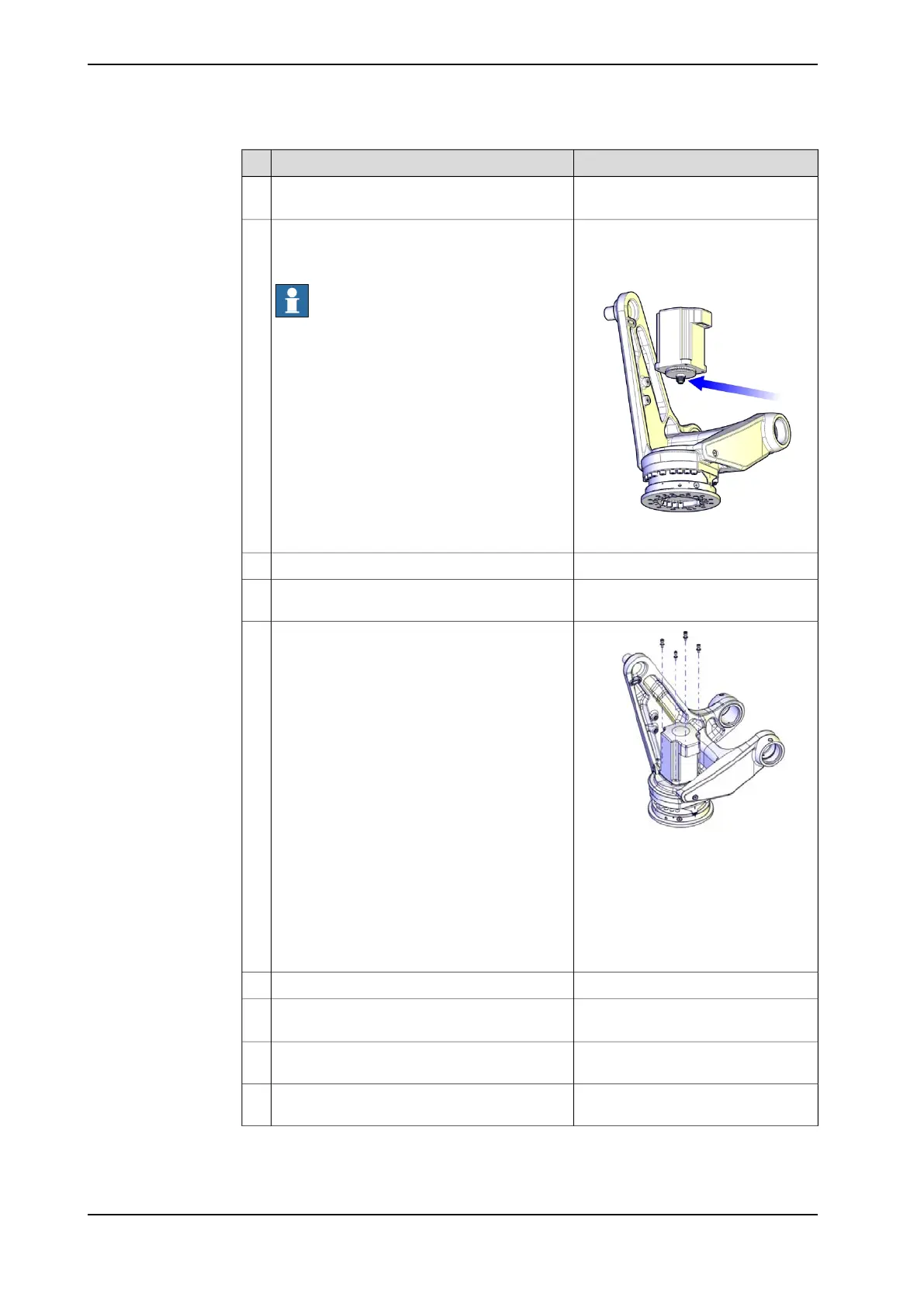
Fit the two guide pins in two of the motor attach-
ment holes.
3
xx1000001108
Lift the motor carefully in place.
Make sure the motor pinion is properly mated
to the gearbox, axis 6.
Note
Make sure the motor is turned the correct way.
See figure!
4
Remove the guide pins.5
Apply locking liquid (Loctite 243) on the attach-
ment screws.
6
xx1000001012
Secure the motor with its four attachment
screws and washers.
Reused screws may be used, providing they
are lubricated as detailed in section Screw joints
on page 347 before fitting.
7
Washers:
• 8.4x16x1.6 quality Steel-A2F
Attachment screws:
• M10 x 40 quality 8.8-A2F
Tightening torque:
• 50 Nm
Disconnect the brake release voltage.8
See section Performing a leak-down
test on page 148.
Perform a leak-down test of the axis 6 gearbox.9
Connect in accordance with markings
on connectors.
Reconnect all connectors in motor axis 6.10
Refit the connections to the UL lamp, if the ro-
bot is equipped with one.
11
Continues on next page
298 3HAC039838-001 Revision: C
© Copyright 2013 ABB. All rights reserved.
4 Repair
4.6.3 Replacing motor, axis 6
Continued