Operation Manual / Power2 800-M / 4 Product description
Page 5 /
© Copyright 2016 ABB. All rights reserved.
Mode of operation of the low-pressure stage (Power2 LP)
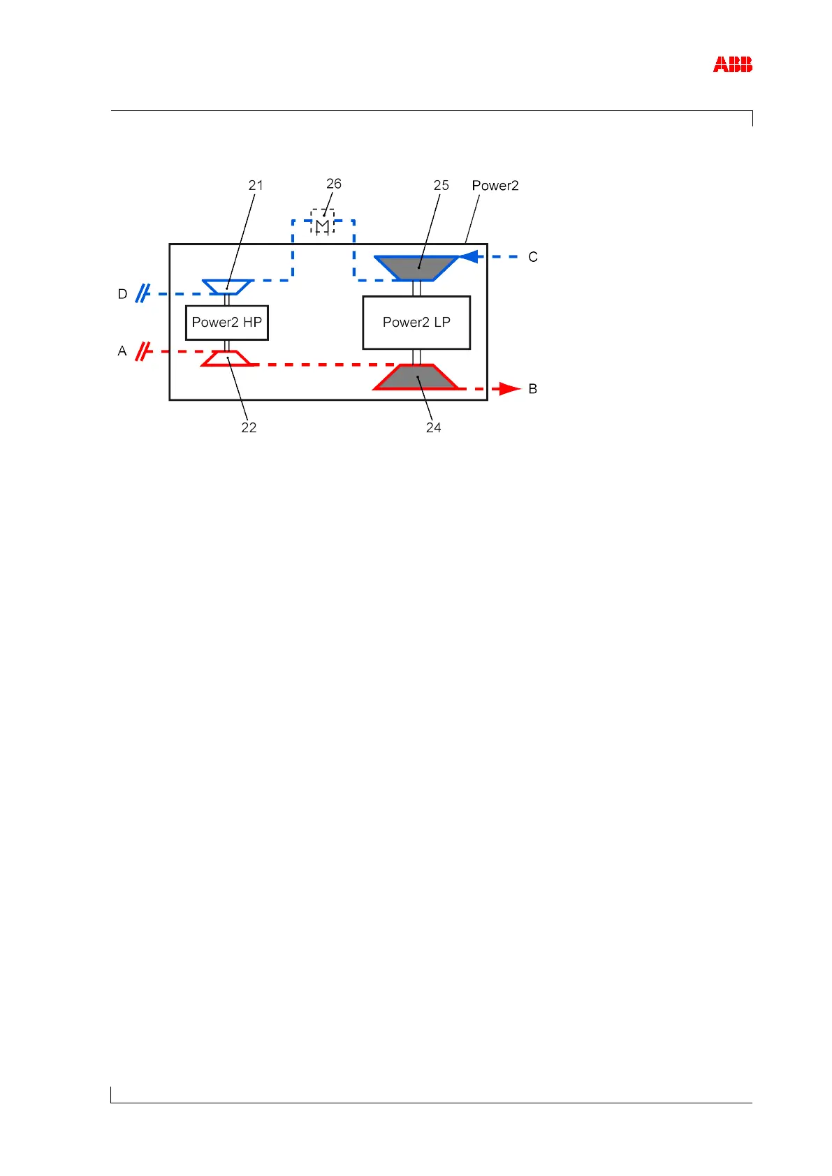
Figure 3: Power2 LP diagram
Power2 Two-stage turbocharging 21 HP compressor
Power2 LP Low-pressure stage 22 HP turbine
Power2 HP High-pressure stage 24 LP turbine
Exhaust gas inlet from internal
combustion engine
26 Intercooler
B Exhaust gas outlet
Air or air/gas mixture inlet
D Air or air/gas mixture outlet and supply to
the charge air cooler
- - - Not included in the ABB Turbo Sys-
tems scope of delivery
The low-pressure stage (Power2 LP) is a turbomachine and consists of the main components
turbine and compressor. These components are installed on a common shaft and form the
rotor.
In the low-pressure stage (Power2 LP) shown in the illustration (see Figure 2), the exhaust
gas coming from the high-pressure stage (Power2 HP) flows through the gas inlet casing (06)
and the nozzle ring (07) and reaches the turbine (08). The LP turbine uses the energy con-
tained in the exhaust gas to drive the rotor. The exhaust gases then reach the atmosphere
through the gas outlet casing (05) and the exhaust gas pipe connected to it.
The rotor runs in two radial plain bearings, which are located between the compressor and the
turbine. The axial bearing is also in the form of a plain bearing. The plain bearings are con-
nected to a central lubricating oil duct which is normally supplied by the lubricating oil circuit of
the engine. The oil outlet lies at the deepest point of the bearing casing (09).
The LP compressor wheel (02) that is connected to the shaft sucks in fresh air or an air/gas
mixture through the filter silencer (01) or the air suction branch. The air is compressed in the
LP compressor and the downstream diffuser (03). The compressed air is passed on to the
intercooler (26) via the compressor casing (10). The air is cooled in the intercooler (26) and
subsequently supplied to the HP compressor (21).
 Loading...


