170 The PQF-Manager user interface Manual Power Quality Filter PQFM
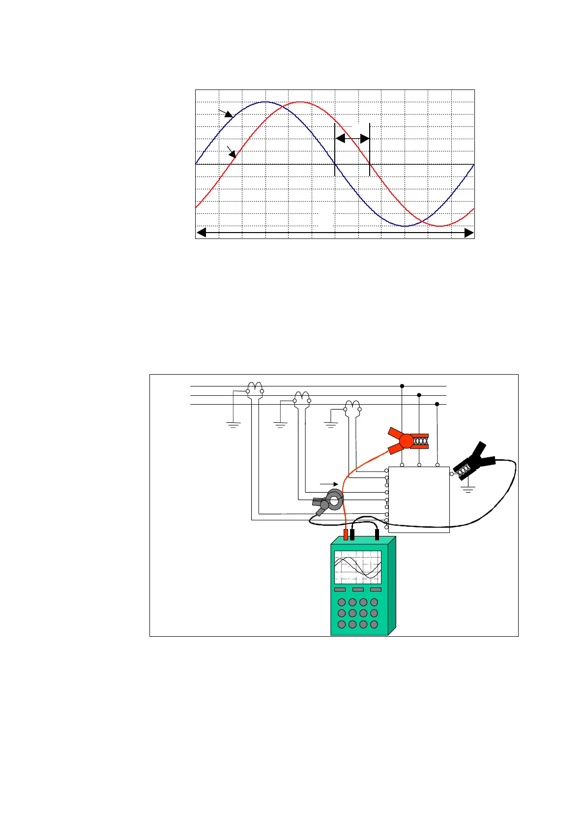
For an inductive and non-regenerative load, the current signal should lag the voltage by
a phase shift lower than 90°.
Figure 95: Phase shift evaluation between two waveforms
8.6.2.3.2Measurement of the CT in phase L2 and L3 (Figure 96 and Figure 97)
The same operations as those described in the previous paragraph must be repeated
with the phase L2 (Figure 96) and phase L3 (Figure 97).
For a balanced load (which is usually the case in most of the three phase systems), the
phase shift should be approximately the same for all the three phases.
X21.2
X21.3
X21.4
X21.5
X21.6
X21.7
X21.8
X21.9
Figure 96: Connection of the scopemeter for checking CT in phase L2
∆T
T
1
U
I1