28 Hardware description Manual Power Quality Filter PQFM
Secondary earth connection point
IGBT inverter with DC capacitors
PQF main controller board
Fixed fuse base main power (cULus version)
Terminals for heat extractio
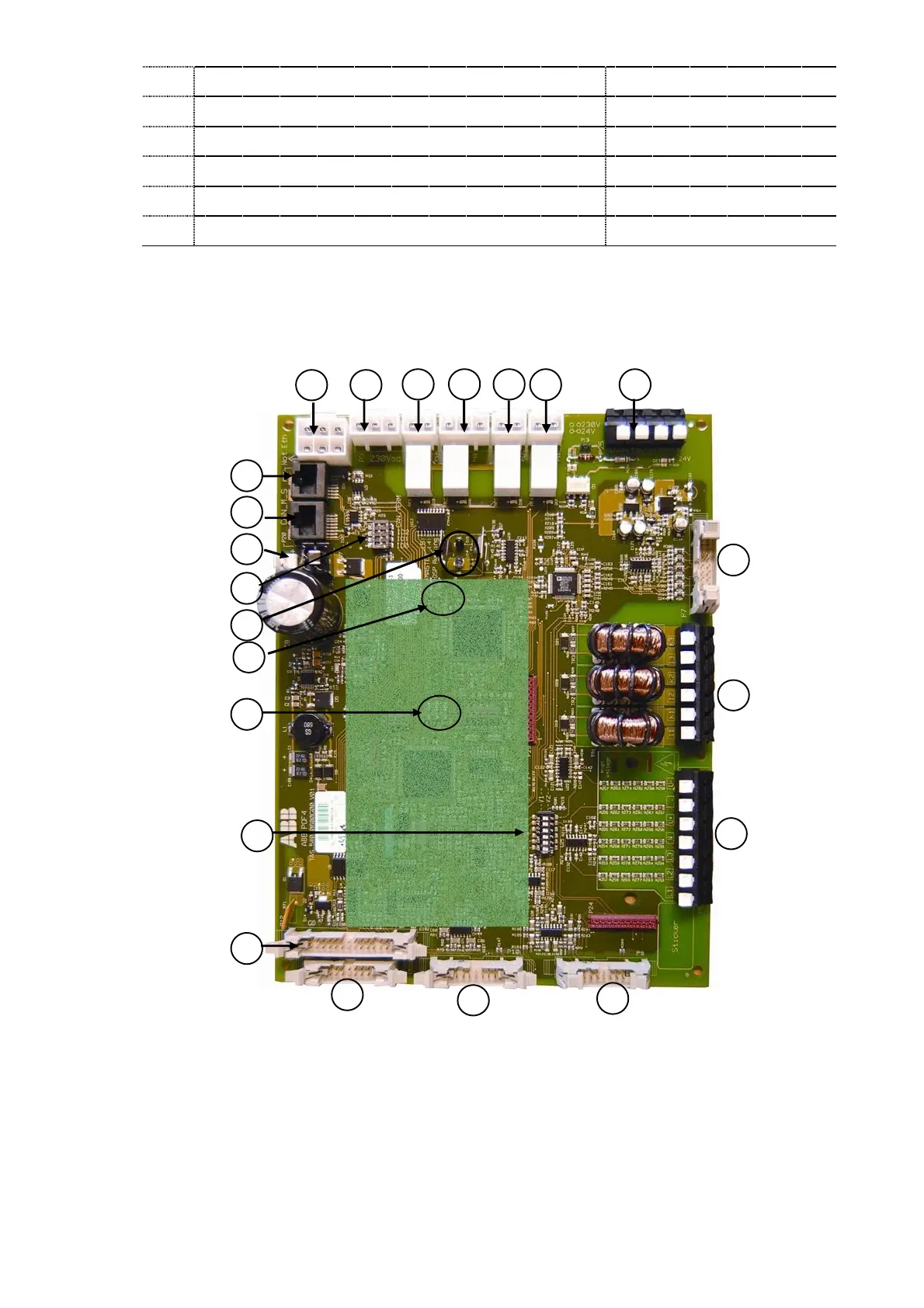
The PQF Main controller board has connectors which are predominantly pre-wired for
use within the filter. However, it also contains a DIP-switch used to set the identification
address and CAN bus connectors for use in a multi-module filter arrangements.
The main controller board is shown in Figure 12.
10
2
6 7 8 9
15
3
12
11
4
13
5
16
17
18
21
22
19
20
1
14
Figure 12: PQF main controller board
The designation of the principal terminals is given in Table 12.