60 Electrical design and installation Manual Power Quality Filter PQFM
o The k (S1) terminal of the line 2 CT (L2, Yellow, V) must be connected to
terminal X214 of the filter.
o The l (S2) terminal of the line 2 CT (L2, Yellow, V) must be connected to
terminal X21-5 of the filter.
o The k (S1) terminal of the line 3 CT (L3, Blue, W) must be connected to
terminal X21-7 of the filter.
o The l (S2) terminal of the line 3 CT (L3, Blue, W) must be connected to
terminal X218 of the filter.
− The CT connection terminal X21 is located at the middle of the top plate of the
filter (Cf. Figure 37).
L2
X21.2
X21.3
X21.4
X21.5
X21.6
X21.7
X21.8
X21.9
To X21.1/X21.2
To X21.4/X21.5
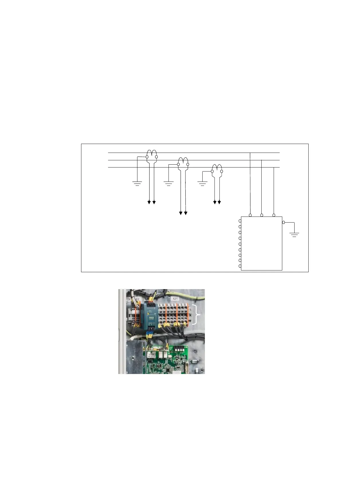
K = P1, L = P2, k = S1, l = S2
Figure 36: Basic CT connection example for a single unit active filter
CT connection terminal X21
(1 = at top, 6 = at bottom)
Figure 37: Location of the CT connection terminal X21 in the PQFM
The terminal block X21 can handle control cable wiring with sections from 2.5 mm² to
10 mm².
In addition to the 6-wire CT cabling approach shown in Figure 36 above, a 4-wire
approach may also be used. This approach is illustrated in Figure 38. In this case the CT
secondary terminal to which the guard circuit is connected is interconnected between
the CTs and also on the filter terminal X21. One common cable is used for this terminal.