Manual Power Quality Filter PQFM Electrical design and installation 61
Note that this cable must be able to withstand three times the secondary current rating
of the CTs. Note that this cable must be able to withstand three times the secondary
current rating of the CTs.
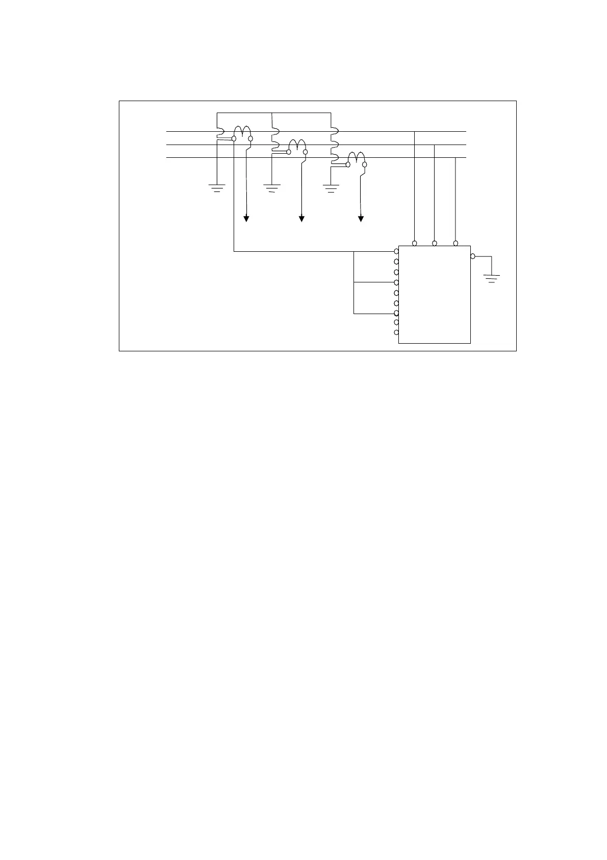
Load side
Supply side
K L
To X21.5
1, L = P2, k = S1, l = S2
X21.1
X21.2
X21.3
X21.4
X21.5
X21.6
X21.7
X21.8
X21.9
Figure 38: Four wires CT wiring approach that may be used with a single unit
PQFM active filter
In case a filter system consists of more than one unit, all units have to be supplied with
the CT measurement information. This is done by cabling the CTs in a daisy chain fashion
between the different units, and looping the last filter CT-terminal back to the CT. This
is illustrated in Section 6.10.4.
In the next sections typical circuit topologies and appropriate corresponding CT
locations are described. The cases considered are:
Case 1: Global compensation – one feeding transformer.
Case 2: Individual compensation – one feeding transformer.
Case 3: Global compensation – transformer busbar not accessible.
Case 4: Two independent feeding transformers.
Case 5: Back-up generator.
Case 6: CT connection location when plain capacitors are present in the network
Case 7: CT connections for the case that detuned capacitor banks are installed adjacent
but downstream to the active filter CTs
Case 8: CT connections for the case that passive filters and active filters are installed in
the same network