- 155 -
000846BG
8 - Maintenance
- Error code
- Error message
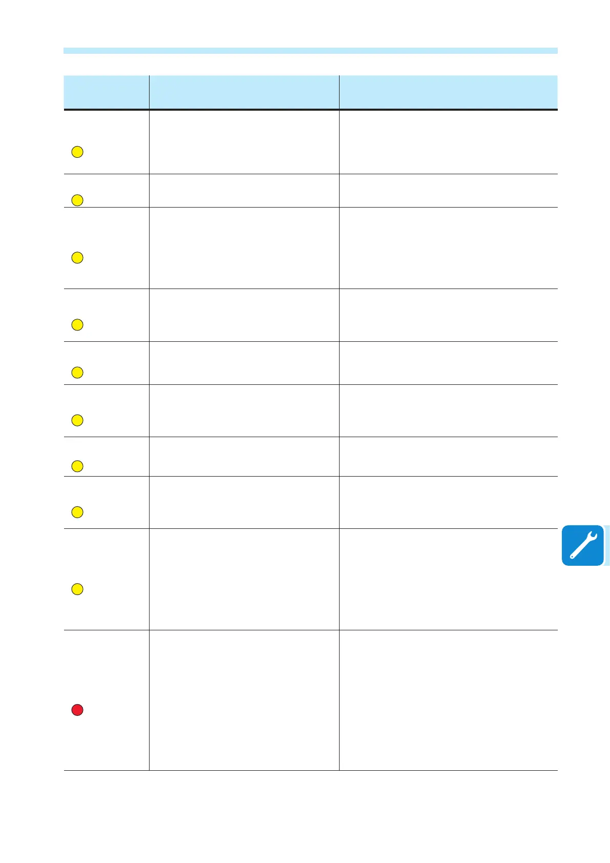
- LED status
Name of Alarm and Cause Solution
- E028
- Internal error
-
Yellow LED
Grid frequency outside of range:
Error in the internal measurement of the grid
frequency (imposed by regulations) to have a
measurement redundancy (2 measurements on the
same parameter carried out by two different circuits).
• Error inside the inverter and cannot be checked externally.
- If the problem persists (once the inverter has been switched
off and back on again), contact customer assistance.
- E029
- Mid Bulk OV
-
Yellow LED
Internal overvoltage on the measurement of the
“Mid bulk”:
Error inside the inverter (only triphase models)
• Error inside the inverter and cannot be checked externally.
- If the problem persists (once the inverter has been switched
off and back on again), contact customer assistance.
- E030
- Internal error
-
Yellow LED
High leakage current (DC side):
- Error on the internal measurement (performed when
the inverter is connected to the grid) of the DC side
(PV generator) leakage current with respect to ground
(required by regulations) to have a measurement
redundancy (2 measurements of the same parameter
carried out by two independent circuits)
• Error inside the inverter and cannot be checked externally.
- If the problem persists (once the inverter has been switched
off and back on again), contact customer assistance.
- E031
- Internal error
-
Yellow LED
Output relay damaged:
Measurement of internal voltage on heads of the
output relay outside of range. There is too great a
difference in voltage between the input and output of
the grid connection relay.
• Error inside the inverter and cannot be checked externally.
- If the problem persists (once the inverter has been switched
off and back on again), contact customer assistance.
- E032
- Internal error
-
Yellow LED
Imbalanced output currents:
Measurement of the unbalance in the output voltage
(made across the three phases) outside of range (only
in three-phase models)
• Error inside the inverter and cannot be checked externally.
- If the problem persists (once the inverter has been switched
off and back on again), contact customer assistance.
- E033
- Undertemperature
-
Yellow LED
Low ambient temperature:
Temperature outside the inverter below -25°C
• Wait for the temperatures to which the inverter is exposed to
return to the operating range.
- If the problem persists, contact customer assistance. You
must remember to wait for the time necessary to allow the
inverter to warm up.
- E034
- IGBT not ready
-
Yellow LED
“IGBT” circuitry not ready:
Error inside the inverter
• Error inside the inverter and cannot be checked externally.
- If the problem persists (once the inverter has been switched
off and back on again), contact customer assistance.
- E035
- Remote Off
-
Yellow LED
Inverter awaiting “remote ON” command:
The inverter has been switched off remotely (remote
OFF) and remains in waiting state for the signal that
will switch it on again (remote ON).
• Switch the inverter back on remotely. If the unit does not
switch on, disable the remote on/off function and switch the
equipment off completely and then switch it on again.
- If the problem persists (once the Remote ON/OFF function
has been reactivated), contact customer assistance.
- E036
- Internal error
-
Yellow LED
Average of the measurements of grid voltage
outside of range:
The average value of the grid voltage (sampled every
10 minutes) does not fall within the permitted ranges.
The grid voltage in the point connected to the inverter is
too high. This may be caused by a grid impedance that
is too high. In the nal stage of the timeout, the inverter
limits the power to check whether the grid voltage
has stabilised into regular parameters. If this does not
happen, the inverter disconnects from the grid
• Check the grid voltage in the connection point to the inverter.
- If the grid voltage differs from the range due to the conditions
of the distribution grid, ask the operator to adjust the grid
voltage. If the operator authorises a change to the inverter's
parameters, agree the new limits with customer assistance.
- E037
- Riso Low
-
Red LED
Low value of the isolation resistance (only with
the “Amorphous” mode activated):
This error can appear only if the “Amorphous” mode
is enabled. This function is enabled only in inverters
equipped with grounding kit and is used to monitor
the voltage at the ends of the grounding resistor. The
error appears when the voltage at the ends of the
resistor connected between ground and pole of the
photovoltaic generator exceeds 30V for more than 30
minutes or 120V for more than one second.
• Check for the presence and correct contact between the
two terminals of the grounding resistance installed inside the
inverter
• Measure the isolation resistance using a megohmmeter
positioned in the photovoltaic array (positive terminal short-
circuited at the negative pole) compared to ground. The
measurement is strongly inuenced by the environmental
conditions, so must be made under the same conditions in
which the error occurred.
- If the value measured is lower than 1 megaohm, a
check must be carried out by a technician/installer on the
photovoltaic generator to identify and eliminate the problem.
- If the value measured is higher than 1 megaohm and the
error signal persists, contact customer assistance.